
Accelerated scan circuitry and method for reducing scan test data volume and execution time

a scan circuit and scan test technology, applied in error detection/correction, instruments, generating/distributing signals, etc., can solve the problems of limiting the effectiveness of scan test, the total number of serial bits that have to be scanned in and out in serial fashion, and the inability to achieve the effect of reducing the number of data volumes

Inactive Publication Date: 2007-03-27
AMERICAN PATENTS LLC +1
View PDF13 Cites 39 Cited by
  • Summary
  • Abstract
  • Description
  • Claims
  • Application Information

AI Technical Summary

Benefits of technology

"The patent text describes a technique for reducing the amount of data needed for scan-based testing of complex integrated circuits. The technique involves compressing the data that is needed to set the state variables of the circuit using a combination of pre-determined bits and pseudo-random bits. By doing so, the data volume is reduced while still being able to set the circuit's state variables to their desired values. This technique helps to decrease the cost of testing complex circuits and improve the efficiency of the testing process."

Problems solved by technology

However, with increasing circuit complexity, which is often measured in terms of the number of state variables (i.e. flip-flops or latches used to implement it) the total number of serial bits that have to be scanned in and out in serial fashion has become a problem.
Parallel scan can help alleviate some of the serial scan, but test time issues limit its effectiveness to the number of independently operable scan chains that can be implemented on a target Integrated Circuit (IC).
Most IC's are limited by the number of their I / O pins that are available for scan and other test purposes.
Unfortunately, shared I / O pins impact the target IC's maximum operating speed.
Furthermore, it is not possible to take advantage of parallel scan unless the Automatic Test Equipment (ATE) that will be used to test the target IC has the ability to feed and observe data on the parallel scan channels simultaneously.
In addition to its limitations as described above, parallel scan, does not address a crucial issue.

Method used


Image

  • Accelerated scan circuitry and method for reducing scan test data volume and execution time
  • Accelerated scan circuitry and method for reducing scan test data volume and execution time
  • Accelerated scan circuitry and method for reducing scan test data volume and execution time

Examples


Embodiment Construction

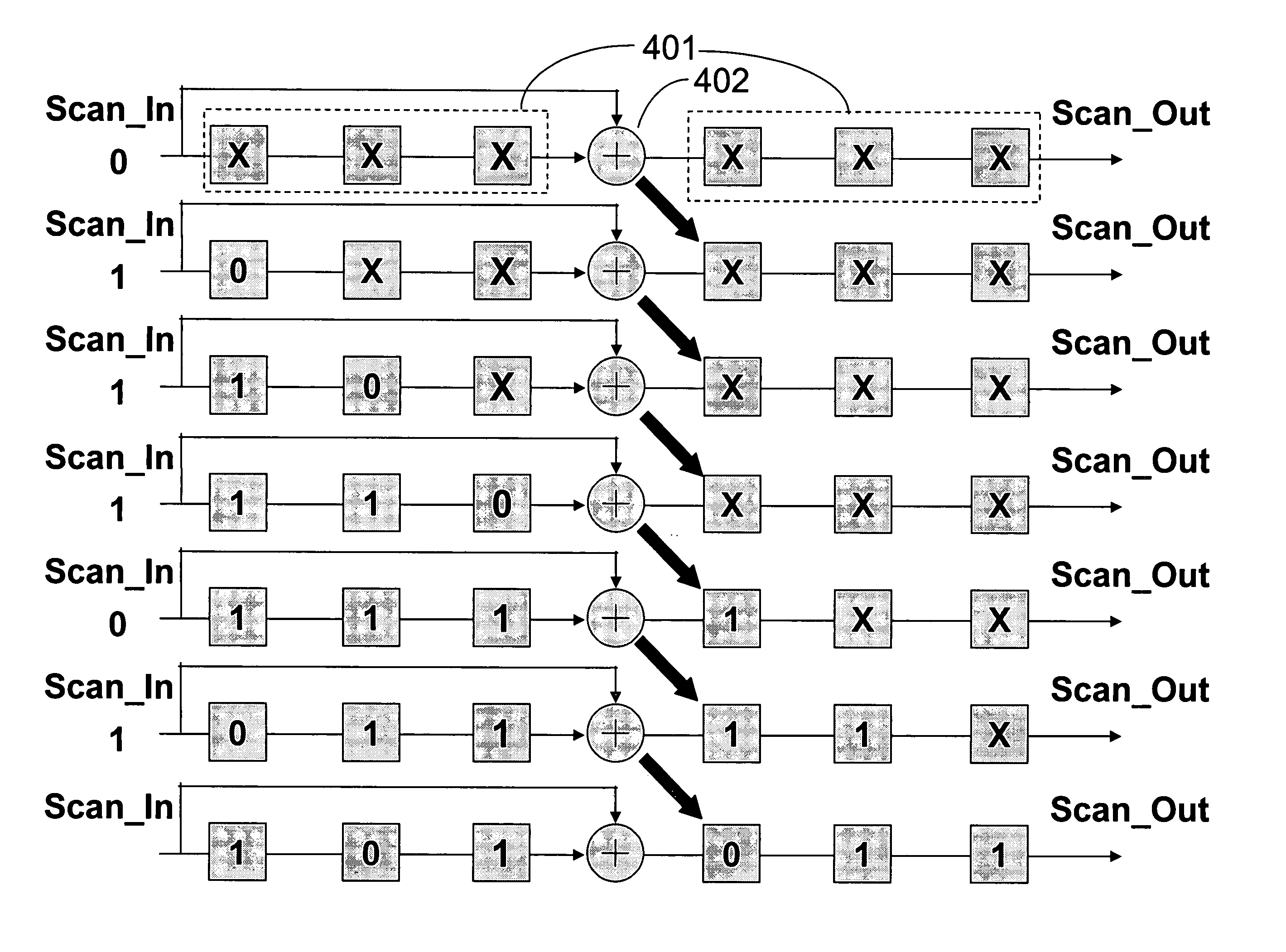
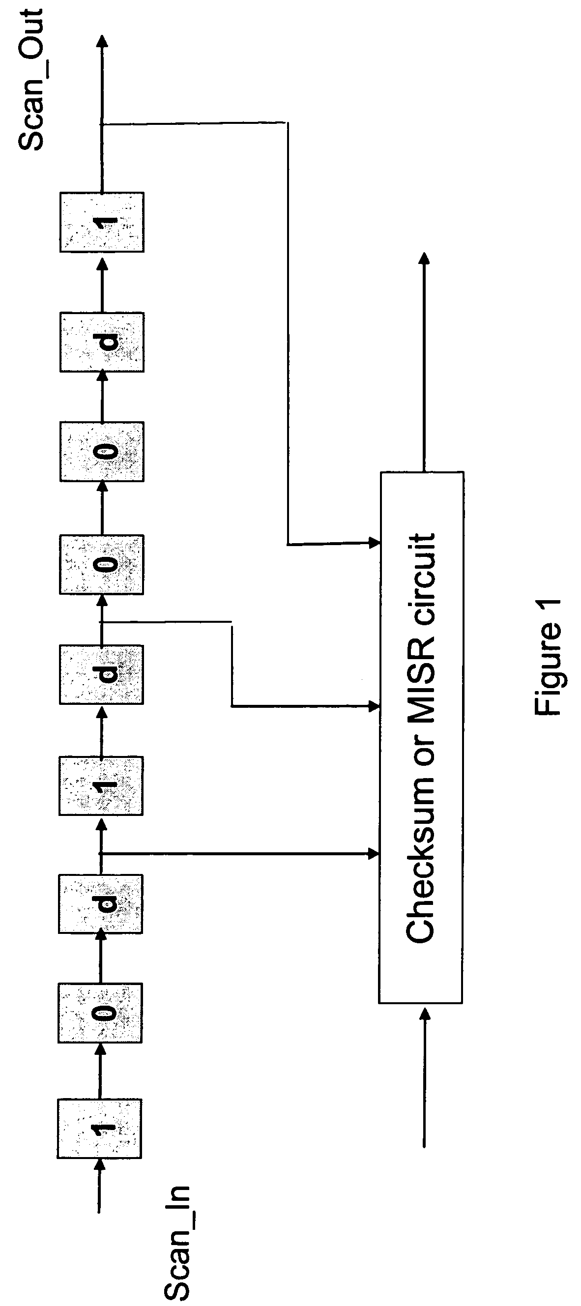
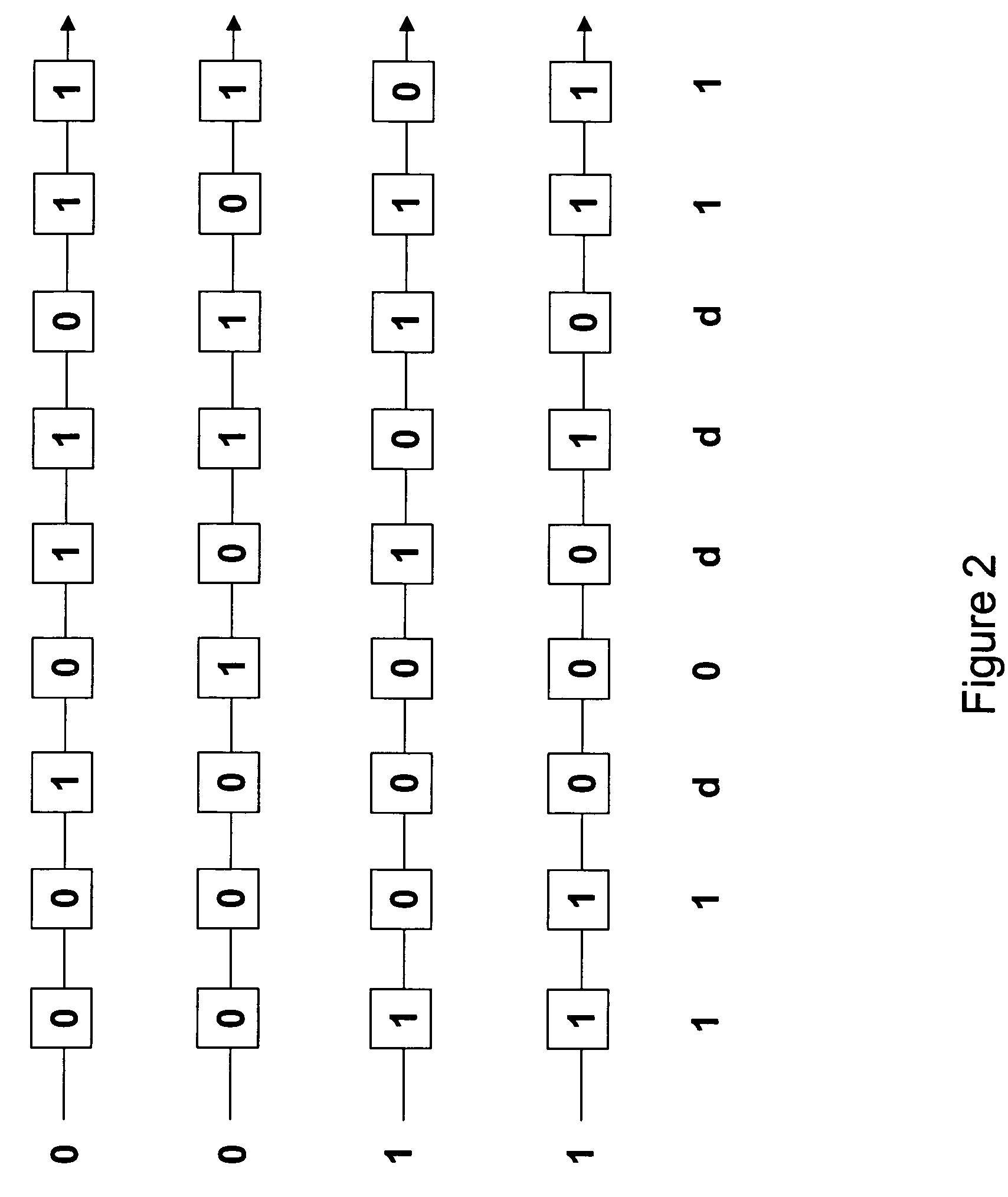
[0041]Traditional approach to scan-based testing employs overlapped Scan_Out of the results for the most recently executes test pattern with the Scan_In for the next test pattern. The primary motivation for doing so has been to take advantage of the ability to feed new serial data (i.e. next test pattern) at one end of the scan-chain while simultaneously receiving the results for the previous test pattern since the two serial streams are of equal length. However, scan-out bits do not all contain useful information regarding the pass / fail status of the previous test vector. Indeed, the only bits where useful information is present are bit positions where at least one fault effect has been propagated. Thus, it is only useful (necessary) to scan-out those bit positions that contain useful information. Here, those bits are referred to as Care_Out bits. It is noted that, typically, each test results vector may contain a small number of Care_Out bits. The remaining bits become set to spec...


PUM


Abstract

An architecture and methodology for test data compression using combinational functions to provide serial coupling between consecutive segments of a scan-chain are described. Compressed serial-scan sequences are derived starting from scan state identifying desired Care_In values and using symbolic computations iteratively in order to determine the necessary previous scan-chain state until computed previous scan-chain state matches given known starting scan-chain state. A novel design for a new flip-flop is also presented that allows implementing scan-chains that can be easily started and stopped without requiring an additional control signal. Extensions of the architecture and methodology are discussed to handle unknown (X) values in scan-chains, proper clocking of compressed data into multiple scan-chains, the use of a data-spreading network and the use of a pseudo-random signal generator to feed the segmented scan-chains in order to implement Built In Self Test (BIST).

Description

CROSS-REFERENCE TO RELATED APPLICATION[0001]This application is a continuation-in-part of U.S. patent application Ser. No. 10 / 351,276, entitled “VARIABLE CLOCK SCAN TEST CIRCUITRY AND METHOD,” filed on Jan. 24, 2003, commonly assigned, and incorporated herein by reference.FIELD OF THE INVENTION[0002]The present invention is related to digital logic testing, particularly additions to scan based digital logic testing, which uses check-sum or signature register logic and exclusive-OR operations on serial shift string logic, and software techniques to reduce test data volume and minimize test time.BACKGROUND AND SUMMARY OF THE INVENTION[0003]Scan-based testing, as described in as described by Eichelberg in U.S. Pat. No. 3,784,907, and Zasio et al. in U.S. Pat. No. 4,495,629, has been the staple of Design for Testability methodology for over 30 years. The technique drives its strength from its ability to replace the state variables (i.e. flip-flops) that make up a sequential circuit by p...

Claims


Application Information

Patent Timeline
Patent Type & Authority Patents(United States)
IPC IPC(8): G01R31/28G01R31/3183G01R31/3185
CPCG01R31/318335G01R31/318385G01R31/318572G01R31/318547G01R31/318552G01R31/318536G01R31/28G01R31/2815G06F1/06G06F1/04
Inventor DERVISOGLU, BULENTCOOKE, LAURENCE H.
Owner AMERICAN PATENTS LLC
Learn More