
Lens cleaner and lens cleaning method for optical disc device

a technology of optical discs and cleaners, which is applied in the direction of mechanical recording, instruments, flat record carriers, etc., can solve the problems of affecting the sound quality, and affecting the quality of reproduction signals, so as to achieve simple and reliable effects

Active Publication Date: 2007-03-27
CLARION CO LTD
View PDF10 Cites 2 Cited by
  • Summary
  • Abstract
  • Description
  • Claims
  • Application Information

AI Technical Summary

Benefits of technology

The present invention provides a simple and inexpensive lens cleaner for an optical disc device that can clean the object lens without causing damage or impurities. The lens cleaner is a cleaning member that makes contact with the object lens on the disc, and there is no recording face that can be the subject of focussing by the object lens. The lens cleaner can be easily operated from the outside of the device, and it is effective in cleaning the object lens in a simple and reliable manner. The cleaning member contains water containing few or little impurities, which ensures reliable cleaning without causing striping patterns. The cleaning member can be adjusted to different optical disc devices by simply positioning it accordingly. The operating member is flexible and does not cause damage to the device. The cleaning method involves inserting the disc into the optical disc device, causing the object lens to move in a direction for making contact with the disc and to attempt to focus on it, halting the playback operation of the disc, performing cleaning of the object lens by means of the cleaning member, and ejecting the disc to the outside of the optical disc device.

Problems solved by technology

In a CD player, the object lens of the optical pick-up for optically reading out signals from a disc can become soiled by adherence of dust, and the like, from the atmosphere, since the lens is exposed constantly.
If soiling of this kind becomes pronounced, then it may cause adverse effects on the quality of the reproduction signal, by producing, for example, sound skipping, noise, degradation of the sound quality, or the like.
If the soiling becomes further severe, then reproduction may become impossible and the device may cease to function.
However, problems of the following kind exist in conventional lens cleaners such as those described above.
Firstly, in the case of a method for cleaning an object lens by causing a lens cleaner disc to rotate by means of the device mechanism, there is a drawback in that cleaning of the object lens cannot be carried out unless the disc rotates.
More specifically, in general CD players are composed in such a manner that, from the viewpoint of preventing inappropriate operation in the event of a defective disc, if the disc management information cannot be read from a disc satisfactorily by the object lens, such disc is regarded to be a defective disc, and all operation of the device including rotation of the disc is halted.
Therefore, if the soiling of the object lens is very bad, then it will not be possible to cause the lens cleaner disc to rotate, and hence cleaning of the object lens will become impossible.
In cases such as these, it is difficult for a general user to clean the object lens by himself or herself, and hence it is necessary that the service department of the manufacturer or the supplier performs the tasks of disassembling the CD player, removing the whole optical pick-up, and replacing it with a new optical pick-up.
Therefore, it is difficult for the user to use the CD player over a long period of time, and furthermore, the economic burden on the user is increased.
However, since the detection of insertion of a lens cleaner is based on detection of the difference in the light exposure by means of the optical pick-up, then if the soiling of the object lens itself is very bad, there is a possibility that misdetection may occur.
Moreover, a special structure is required in the optical disc device in order to detect the lens cleaner, and hence the device becomes more complicated.
Furthermore, even if it is possible to clean the object lens by rotating the disc, since the bristle brushes projecting from the disc also make contact with other regions in addition to the object lens, then the cover of the optical pick-up, and the like, forms an obstacle and the bristle brushes do not make satisfactory contact with the object lens, and hence there is a possibility that effective cleaning will no longer be achievable.
Moreover, there is also a possibility that secondary problems may arise, for instance, that grease in the vicinity of the optical pick-up may conversely be applied to the object lens by means of the bristle brushes.
In particular, in the case of DVD players, which have become remarkably widespread in recent years, the object lens of the optical pick-up is extremely small, and therefore it is highly susceptible to soiling and effective measures against soiling are required.
Therefore, in a rotary type lens cleaner such as those described above, the bristle brushes make contact with members which are disposed in the narrow space in the periphery of the optical pick-up and dirt on these is liable to become adhered to the optical pick-up.
S63-313378 described above, a cleaning cartridge has been proposed whereby, rather than using a rotary type device, cleaning is performed manually by means of an operating lever which is exposed to the outside of the device, but the optical disc devices to which a cartridge type system can be applied are limited.
Furthermore, there is also a possibility that the cartridge may impact with the optical pick-up or other members, and it is not appropriate for compact devices.
In particular, there is a possibility that the insertion hole or members in the proximity thereof may be damaged by contact with the rod-shaped operating lever.
Moreover, since it is necessary to adopt a constitution wherein the actual box-shaped cartridge itself corresponds to the interior of the optical disc device, then the constitution of the cartridge becomes complex, liable to fracturing, and incurs manufacturing costs.

Method used


Image

  • Lens cleaner and lens cleaning method for optical disc device
  • Lens cleaner and lens cleaning method for optical disc device
  • Lens cleaner and lens cleaning method for optical disc device

Examples


Embodiment Construction

[0036]Below, an embodiment of the present invention is described in concrete terms with reference to FIG. 1 to FIG. 6.

1. Constitution of the Lens Cleaner

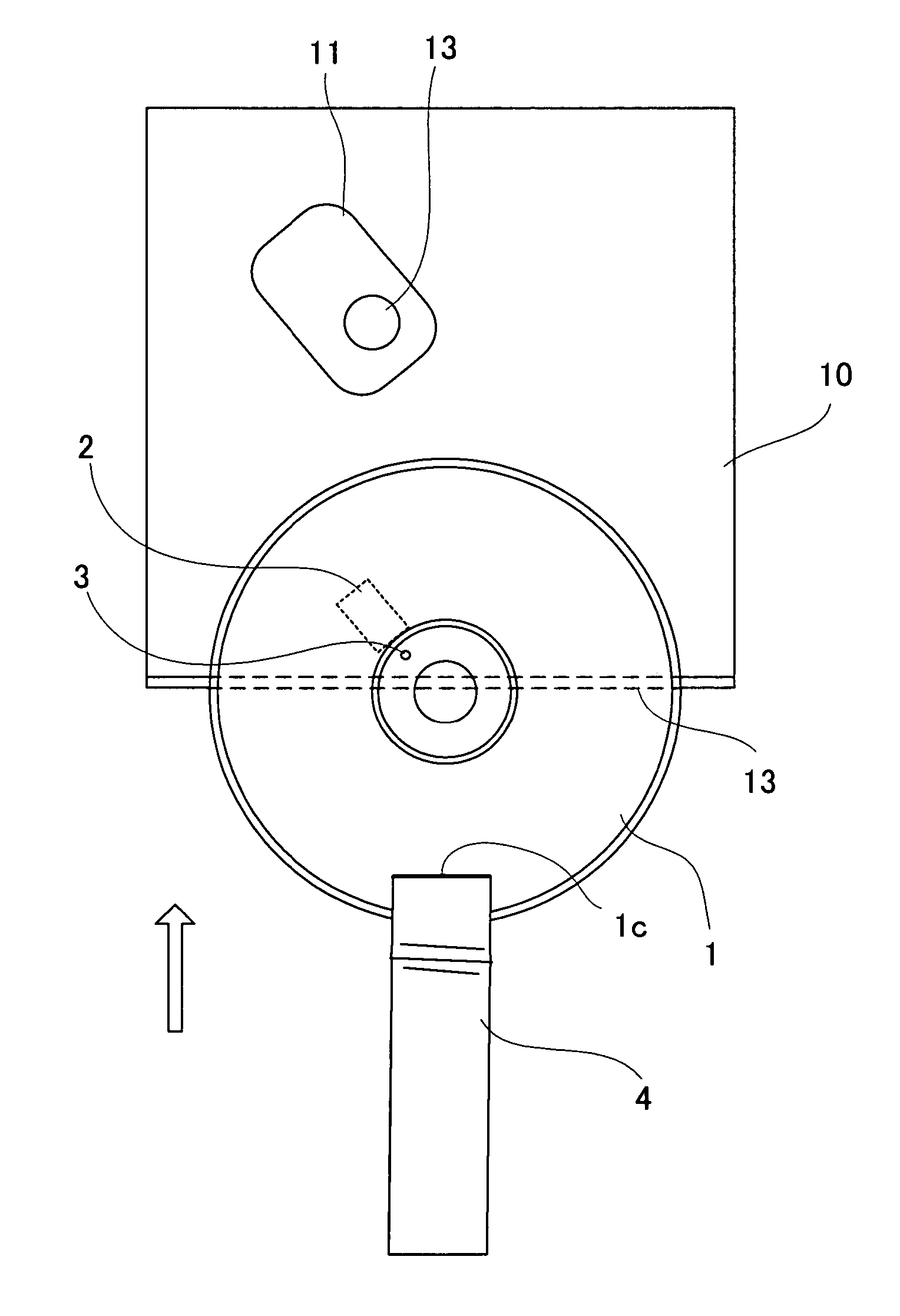
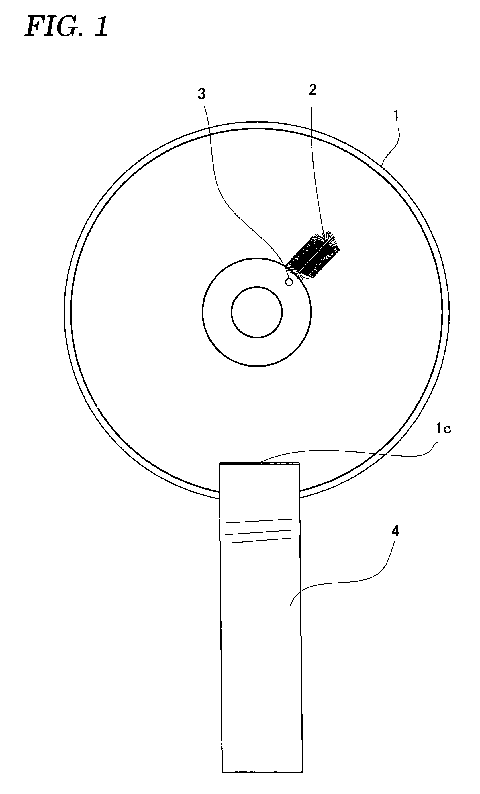
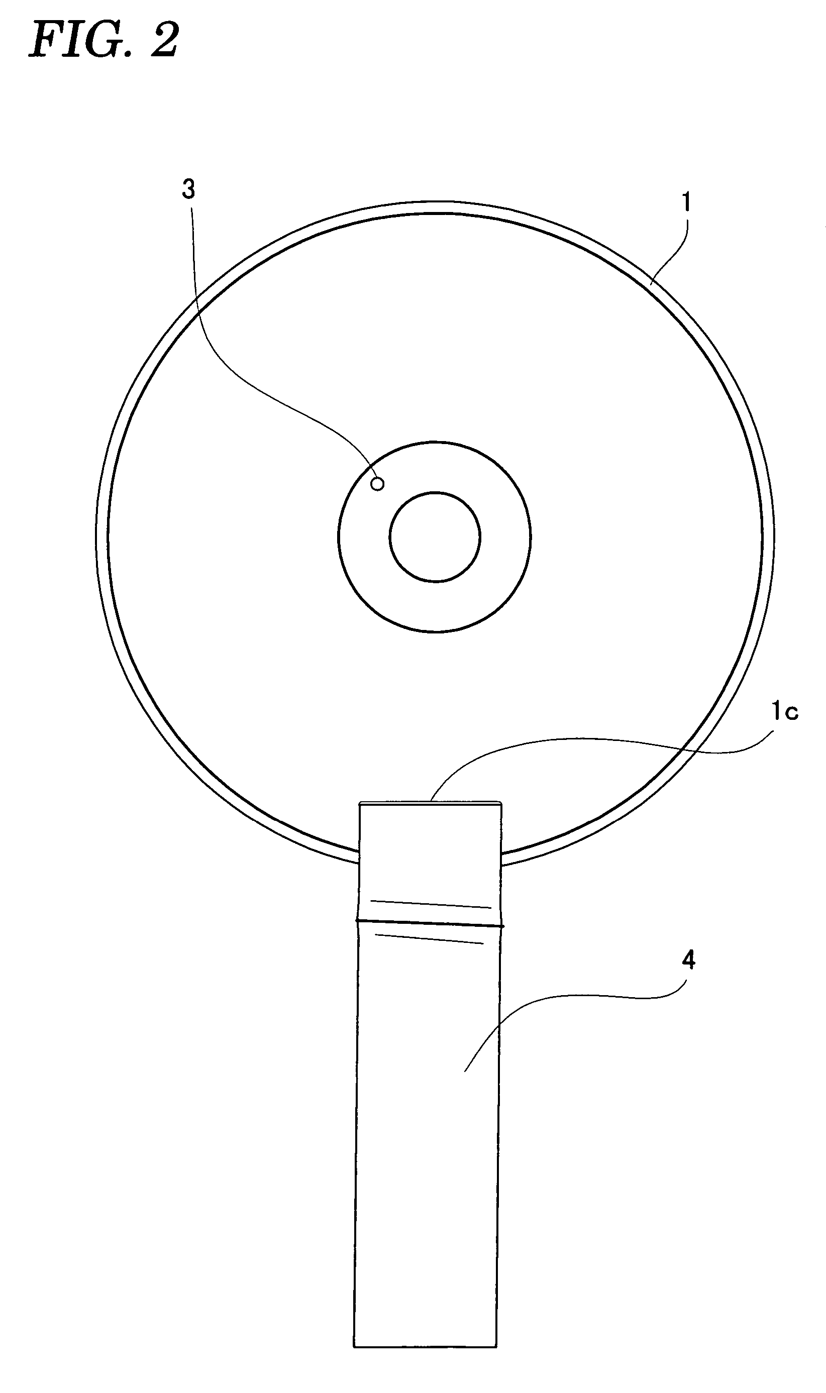
[0037]FIG. 1 and FIG. 2 are plan views showing a lens cleaner relating to one embodiment in which the present invention is applied, FIG. 1 illustrates a cleaning face and FIG. 2 illustrates a label display face. As shown in FIG. 1, the lens cleaner relating to the present embodiment uses a disc 1 which is of substantially the same specification as a CD, and a cleaning face is constituted by installing bristle brushes 2, which are cleaning members, on the face corresponding to the signal reading face of the CD. An operating ribbon 4 for operating the disc is installed in a portion of the disc 1 in the vicinity of the edge thereof. Below the constitution of each portion of the disc is described in more detail.

[0038]Firstly, as shown in FIG. 1 and FIG. 3, a bristle brush 2 is constituted by providing groove holes 1a, 1b formed in two p...


PUM

PropertyMeasurementUnit
reflectionaaaaaaaaaa
flexibleaaaaaaaaaa
sizeaaaaaaaaaa

Abstract

By not recording a signal which can be the subject of focussing on a disc, a simple and inexpensive lens cleaner is provided which is able to perform cleaning of an object lens in a simple and reliable manner, without causing the disc to rotate, even in a standard disc device. In order to clean the object lens of the optical disc device, a bristle brush which makes contact with the object lens is provided on the disc, an operating ribbon for operating the disc from the outside of the device is attached to the disc, and no recording face that can be the subject of focussing by the object lens is provided, or alternatively, no signal that can be the subject of focussing by the object lens is recorded, on the face of the disc adjacent to the object lens.

Description

BACKGROUND OF THE INVENTION[0001]1. Field of the Invention[0002]The present invention relates to an optical disc device such as a CD player or the like, and more particularly, to a lens cleaner for cleaning the object lens of an optical pick-up for optically reading out signals from a disc.[0003]2. Description of the Related Art[0004]In a CD player, the object lens of the optical pick-up for optically reading out signals from a disc can become soiled by adherence of dust, and the like, from the atmosphere, since the lens is exposed constantly. If soiling of this kind becomes pronounced, then it may cause adverse effects on the quality of the reproduction signal, by producing, for example, sound skipping, noise, degradation of the sound quality, or the like. If the soiling becomes further severe, then reproduction may become impossible and the device may cease to function. Therefore, from the viewpoint of maintaining the level of cleanliness of the surface of the object lens at or ab...

Claims


Application Information

Patent Timeline
Patent Type & Authority Patents(United States)
IPC IPC(8): G11B7/085B08B11/00G11B23/00G11B7/12G11B7/121G11B33/00G11B33/14
CPCG11B7/1201G11B7/121
Inventor KOBAYASHI, HIDEYA
Owner CLARION CO LTD
Learn More