Francis turbine

a turbine and turbine blade technology, applied in the field of turbine blades, can solve problems such as loss of hydraulic efficiency, and achieve the effects of reducing secondary flow, improving blade shape, and reducing cavitation

Active Publication Date: 2007-04-03
KK TOSHIBA
View PDF12 Cites 24 Cited by
  • Summary
  • Abstract
  • Description
  • Claims
  • Application Information

AI Technical Summary

Benefits of technology

[0010]Accordingly, an advantage of an aspect of the present invention is to provide a Francis turbine with an improved shape of blades which can reduce cavitations generated on the surface of the blades or reduce the secondary flow around the blades.

Problems solved by technology

Especially, it is known that secondary flow, which is a flow not being along a flow line, distorts a pressure distribution on the blades and results in loss of hydraulic efficiency.

Method used


Image

  • Francis turbine
  • Francis turbine
  • Francis turbine

Examples


first embodiment

[0024]A first embodiment in accordance with the present invention will be explained with reference to FIGS. 1 to 4.

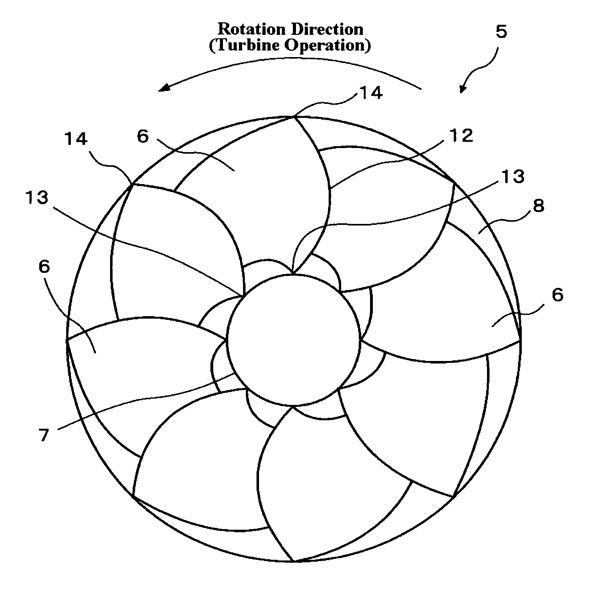
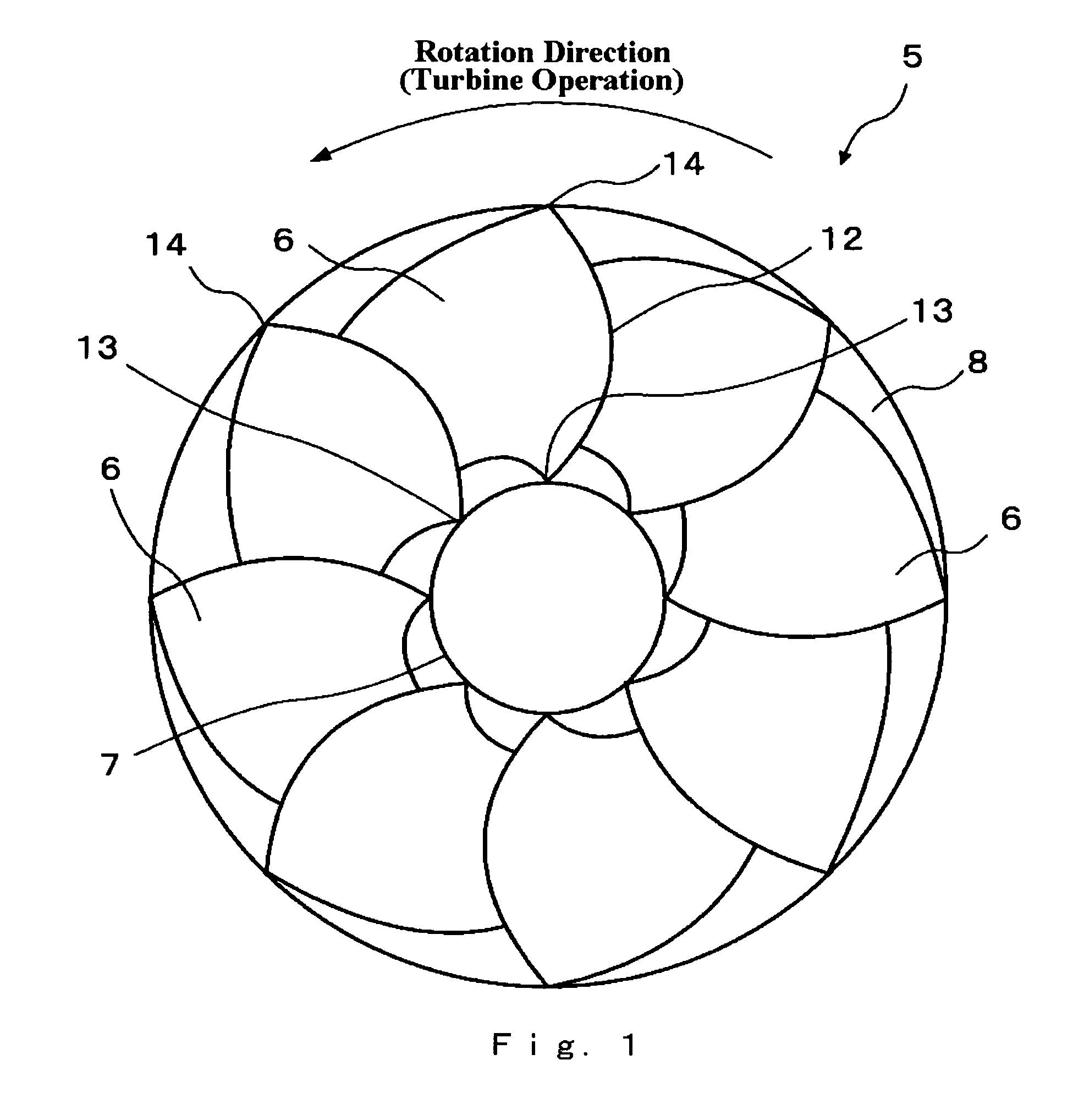
[0025]FIG. 1 is a plan view of a Francis turbine runner 5 seen from a runner outlet side, according to a first embodiment of the invention. In other words, FIG. 1 shows projected profiles of the outlet of the Francis turbine runner on a plane that is perpendicular to a rotation axis of the Francis turbine runner. A plurality of runner blades (runner vanes) 6 are disposed in a circumferential array on a crown 7. A head side of the runner blade 6 is supported by the crown 7 at a crown edge 13 (also referred to as a crown connecting point). A bottom side of the runner blade 6 is supported by a band 8 at a band edge 14 (also referred to as a band connecting point). FIG. 1 shows the Francis turbine runner 5 having eight runner blades 6 disposed therein. Thus, band 8 is coaxially coupled to crown 7 by blades 6 and a rotation shaft (not shown) is connected at the center of cro...

second embodiment

[0043]A second embodiment in accordance with the invention will be explained referring to FIGS. 5 to 9.

[0044]FIG. 5 is a plan view of the blades seen from an outlet side of the turbine (band side) with the band being removed from the runner. In FIG. 5, a symbol 20 indicates a Francis turbine runner. A symbol 21 indicates a blade, a symbol 22 indicates a crown. Same as first embodiment, Francis turbine runner 20 includes crown 22, a plurality of blades 21 and a band (not shown). A symbol 24 indicates a leading edge, which is an outer end of blade 21, in which water comes during the turbine operation. A symbol 31 indicates a trailing edge, which is an inner end of blade 21, where water flows out during the turbine operation. A symbol 28 indicates a rotating shaft (spindle) connected to crown 22. A rotation center of rotating shaft 28 is referred to as ◯ (also referred to as CL), which is corresponding to a rotation axis. Same as the first embodiment, FIG. 5 shows projected profiles of...


PUM


Abstract

A Francis turbine with an improved shape of blades, which can reduce cavitations generated on the surface of the blades or reduce the secondary flow around the blades, is provided. A Francis turbine comprises a rotating shaft, a crown, a plurality of blades, and a band. The crown can rotate with the rotating shaft. The blades are circumferentially arranged on the crown, each of which including an inner end as a trailing edge. The band is coaxially coupled with the crown by the blades. The rotating shaft, the crown, the blades, and the band as a whole rotate toward a turbine direction during a turbine operation. A projected profile of the trailing edge on a perpendicular plane, which is perpendicular to a center axis of the rotating shaft, is curved toward a direction opposite to the turbine direction at least in the crown side.

Description

CROSS REFERENCE TO RELATED APPLICATION[0001]This application is based upon and claims the benefit of priority from prior Japanese Patent Applications No. 2003-171108 filed on Jun. 16, 2003, and No. 2003-291266 filed on Aug. 11, 2003, the entire contents of which are incorporated herein by reference.FIELD OF THE INVENTION[0002]This invention relates to a Francis turbine that is used for a hydraulic turbine or a pump, and in particular, a Francis turbine having blades with an improved shape on a trailing edge.BACKGROUND[0003]A Francis turbine is used in a hydraulic machine, including a reversible pump-turbine, for power generation.[0004]A conventional Francis turbine runner is described in U.S. Pat. No. 4,479,757. This conventional Francis turbine runner includes blades whose inlet (a leading edge) shape is curved toward a direction opposite to a rotating direction of a turbine operation from a band side to a crown side.[0005]Another conventional Francis turbine runner is described in...

Claims


Application Information

Patent Timeline
Patent Type & Authority Patents(United States)
IPC IPC(8): F03B3/02B63H1/16F01D5/04F01D5/14F03B3/10F03B3/12
CPCF03B3/125F05B2240/301F05B2250/71Y02E10/223Y10S416/02Y02E10/20
Inventor ENOMOTO, YASUYUKISUGISHITA, KANEOKUROSAWA, SADAOSUZUKI, TOSHIAKINAKAMURA, TAKANORI
Owner KK TOSHIBA
Why Eureka
Try Eureka