Modulator for digital amplifier

a digital amplifier and modulator technology, applied in pulse manipulation, pulse characteristics measurement, pulse technique, etc., can solve the problems of quantization noise of digital pwm signals, complex modulator, and non-linear process, and achieve the effect of increasing the cost of the complex modul

Inactive Publication Date: 2007-04-03
OBRIEN AUDIO
View PDF37 Cites 20 Cited by
  • Summary
  • Abstract
  • Description
  • Claims
  • Application Information

AI Technical Summary

Problems solved by technology

Because the pulse width may vary only in discrete steps, digital PWM signals suffer from quantization noise and may require noise shaping or dithering to reduce at least the apparent quantization noise.
This, however, is a non-linear process because the input waveform changes after the modulator has determined the preferred output pulse width.
To overcome the error associated with this process, a linearizer may be used, but the resulting complexity of the modulator greatly increases its cost.
Digital PWM also suffers from minimum and maximum pulse width limitations.
Otherwise, the output stage can not track the desired PWM output signal.
These minimums ultimately limit the output power attainable with a given power supply voltage.
Furthermore, pulses greater than the maximum pulse width may unduly burden the power supply or require excessive cooling of the output transistors.

Method used


Image

  • Modulator for digital amplifier
  • Modulator for digital amplifier
  • Modulator for digital amplifier

Examples


embodiment 1200

[0055]FIG. 12 shows yet another alternative embodiment 1200. In this embodiment, a digital input signal is applied to the IN port of subtractor 1202. The remaining elements between subtractor 1202 and the output signal OUT are configured and operate the same as the same elements in FIG. 11. In the embodiment shown in FIG. 12, however, the feedback loop feeds the signal from output stage 510 to loop gain amplifier 1104, which attenuates the signal to conform to the levels of the input signal IN, and applies the attenuated signal to the cascade combination of analog filter 1106 and A / D converter 1108. The output signal of the analog-to-digital converter is the second input signal to subtractor 1202. As described above with reference to FIG. 11, in an alternative embodiment, the feedback loop can be taken after output filter 512. In yet another alternative embodiment, both the output stage 510 and the output filter 512 may provide feedback signals which are summed (not shown) before be...

embodiment 1300

[0056]As described above in connection with FIGS. 1 to 5, the input signal IN may be, for example, the output signal generated by an analog sigma-delta modulator. An embodiment 1300 of such an analog sigma-delta modulator is shown in FIG. 13. Typically, analog sigma-delta modulators are used as a component in a sigma-delta analog-to-digital converter. In this embodiment of the invention, the sigma-delta modulator is used to generate a one-bit sampled signal, having digital signal levels, which is applied to the subtractors 302, 402 or 502 of the modulators shown in FIGS. 3A through SB.

[0057]In FIG. 13, an analog input signal is applied to the input port of summing element 1302, the output signal of which is coupled to the cascade combination of filter amplifier 1304 and filter 1306. The filter 1306 may, for example, have the same structure as filter 306, shown in FIG. 7. The output signal of filter 1306 is coupled to comparator 1308 which operates in the same way as comparator 308 i...


PUM


Abstract

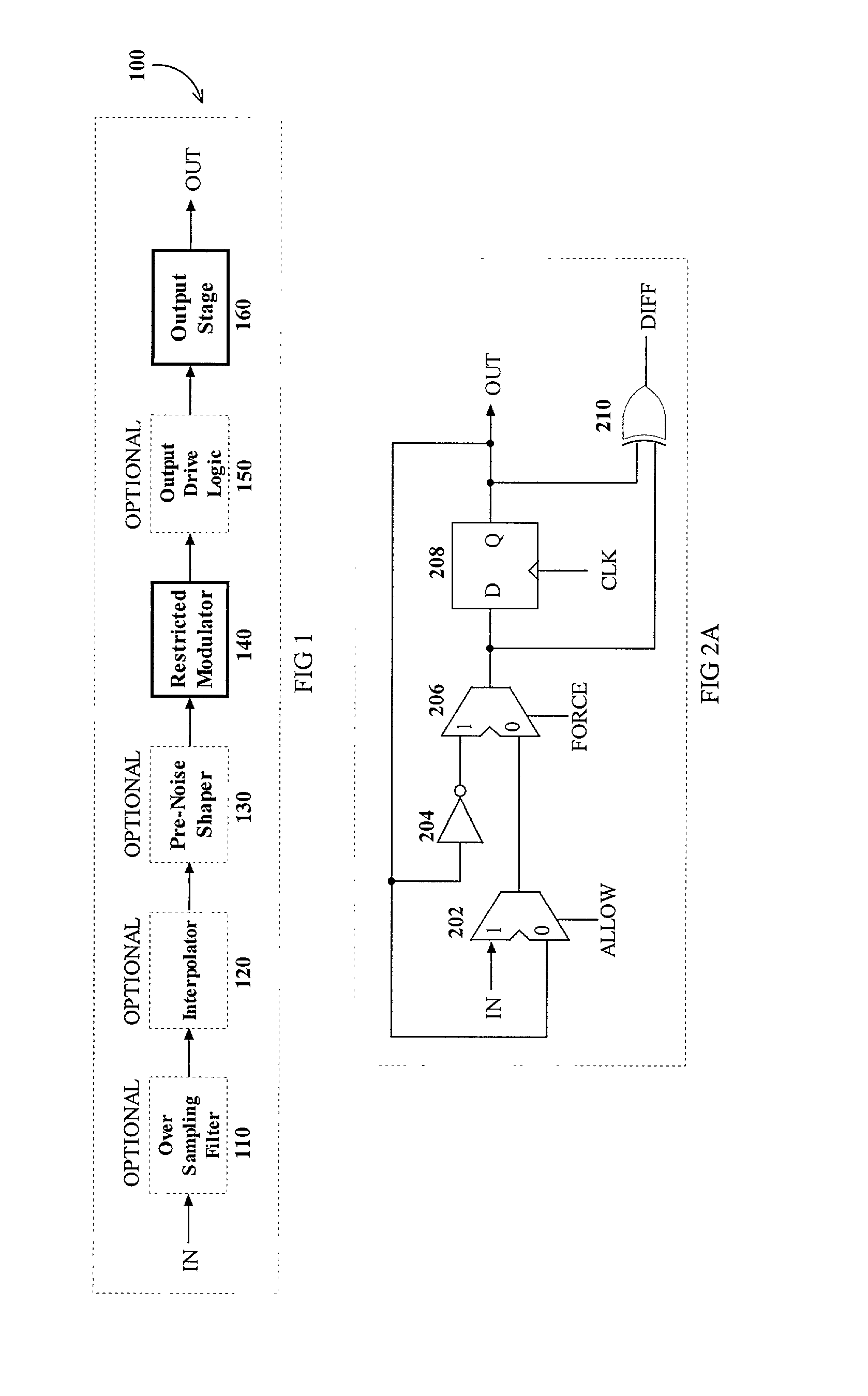
A digital modulator for driving a digital amplifier. The digital modulator has a subtractor which receives a digital input signal. A filter amplifier receives the output of the filter amplifier and is tuned to an idle frequency of the digital modulator. The digital modulator includes a delay element and a digital comparator. The digital comparator receives the output from the filter and applies it to the delay element. A feedback loop couples the output of the delay element to the subtractor.

Description

CROSS REFERENCE TO RELATED APPLICATION[0001]This application claims the benefit under Title 35 U.S.C. § 119(e) of U.S. Provisional Application No. 60 / 308,005 filed on Jul. 26, 2001, the contents of which are incorporated by reference.FIELD OF THE INVENTION[0002]The present invention relates to digital amplifiers and particularly to a digital modulator including a restricted digital modulator, configured to drive a digital audio power amplifier.BACKGROUND OF THE INVENTION[0003]Pulse Width Modulation (PWM) models an analog input signal as a sequence of pulses having a fixed amplitude and period but having a variable pulse width. The time integral of the PWM signal closely approximates the analog input signal.[0004]Many digital amplifiers and some analog amplifiers use PWM to convert incoming audio signals to a pulse train and then increase the amplitude of the pulse train in order to amplify the input signal. Analog PWM is performed by analog circuits that provide a continuously varia...

Claims


Application Information

Patent Timeline
Patent Type & Authority Patents(United States)
IPC IPC(8): H03K9/00H03F3/217H03K7/08
CPCH03F3/2171H03F3/2173H03K7/08H03F2200/331
Inventor O'BRIEN, THOMAS J.
Owner OBRIEN AUDIO
Why Eureka
Try Eureka