System and method for generating trace data in a computing system

Active Publication Date: 2007-04-03
ORACLE INT CORP
View PDF13 Cites 73 Cited by
  • Summary
  • Abstract
  • Description
  • Claims
  • Application Information

AI Technical Summary

Benefits of technology

[0033]In this embodiment, multiple data generation portions can share a single data record portion. One consequence of this is that the diagnostic information from the different data generation portions can then all be stored at a single region in main memory. Not only does this lead to the efficient use of storage space, but it also makes it easier for any diagnostic programs to locate and acces

Problems solved by technology

The complexity of modern computer systems is such that it can be very difficult for designers to fully understand every detail of the operation, and in particular the full interaction of all the different hardware components.
Thus although the basic operation of individual hardware components might be known, a large-scale program may conceivably utilise a vast number of operational sequences for any given device, and generate a huge number of interactions between the different devices.
It can be very difficult to predict on a purely abstract basis which particular sequences or interactions will be most utilised in practice.
However, although software emulators are very powerful in terms of functionality, they suffer from two significant drawbacks.
The first is that they can be difficult and time consuming to develop.
In this respect they represent an additional expense over and above the cost of producing the new hardware itself.
In other words, if a problem is known or suspected to exist purely in relation to one particular hardware component, it can be difficult to construct a simulator simply for this one component.
A second drawback is that the operation of a software emulator is much slower than the corresponding hardware (which is of course why machines are implemented in hardware rather than in software).
This can make it a lengthy and time-consuming process to obtain the results required for proper analysis of the hardware system.
In addition, it can make it difficult to properly test a typical real-life application, if this is a program that needs to operate in real-time or

Method used


Image

  • System and method for generating trace data in a computing system
  • System and method for generating trace data in a computing system
  • System and method for generating trace data in a computing system

Examples


Embodiment Construction

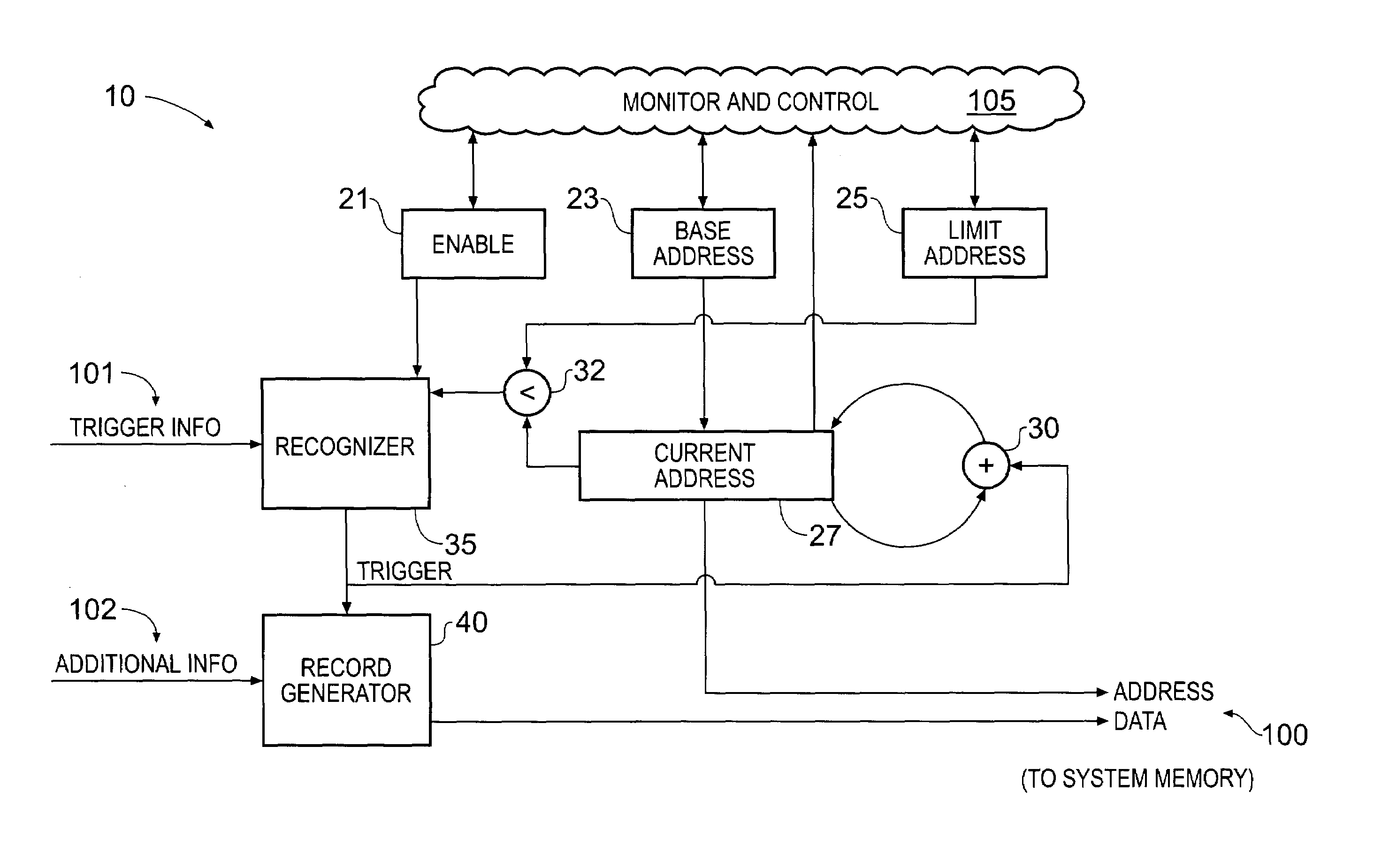
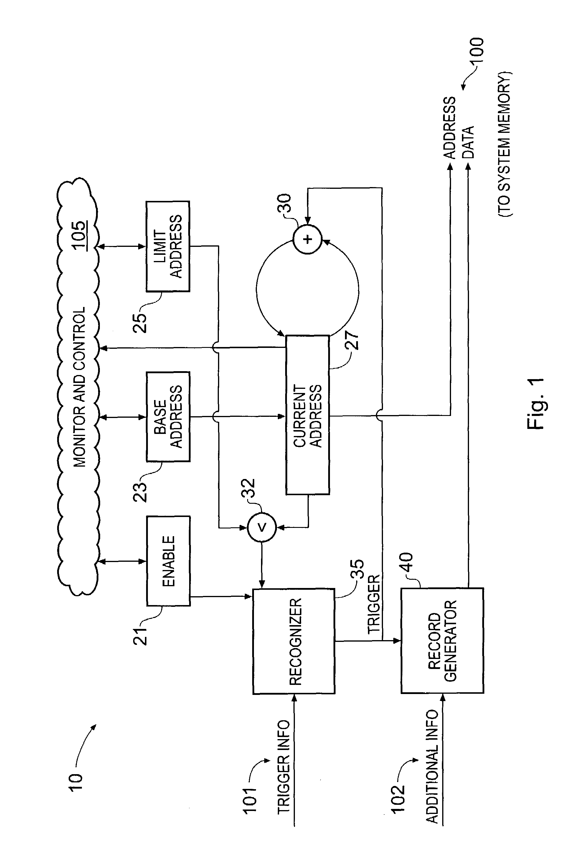
[0042]FIG. 1 illustrates a trace unit 10 in accordance with one particular embodiment of the present invention. The trace unit serves to intercept desired diagnostic information and to write this information out to main memory, as will now be described.

[0043]As shown in FIG. 1, trace unit 10 includes two address storage registers. The first of these registers 23 is used for storing a base address. The second register 25 is used for storing a limit or end address. Together, these two registers 23, 25 define a region of system memory into which the trace unit will output diagnostic information. (It will be appreciated that this memory region could also be defined by storing its base address and size, rather than the base address and end address).

[0044]In operation, the desired values for the base address and limit address are written into register 23 and register 25 respectively by the monitor and control system 105. The base and limit addresses stored in registers 23 and 25 may also ...


PUM


Abstract

A hardware trace unit is integrated into a computer system that has a main memory. The trace unit includes registers that contain information defining a location in main memory, and has an input connection. This is used to eavesdrop on communications in the computer system, thereby obtaining information about the state and/or operation of the system. A trigger mechanism then compares the information received against one or more trigger conditions, such as whether a particular event has occurred. Responsive to the trigger conditions being satisfied, the trace unit generates an output record containing diagnostic information. This is sent for storage in the main memory of the computer at the location defined in the registers.

Description

FIELD OF THE INVENTION[0001]The present invention relates to the acquisition of trace or diagnostic information for monitoring the operation and performance of a computer system.BACKGROUND OF THE INVENTION[0002]The complexity of modern computer systems is such that it can be very difficult for designers to fully understand every detail of the operation, and in particular the full interaction of all the different hardware components. Note that such components may be physically separate devices, or logically separate portions of a single device (for example, a specific functional area on a processor or other semiconductor device). Nevertheless, such an understanding is important if the performance of the system is to be improved or if any potentially erroneous behaviour is to be corrected.[0003]One particular area of interest is how the system operates for a “real-life” application. Thus although the basic operation of individual hardware components might be known, a large-scale progr...

Claims


Application Information

Patent Timeline
IPC IPC(8): G06F11/00G06F11/34G06F11/36
CPCG06F11/3466G06F11/3636G06F11/348
Inventor HARRIS, JEREMY G
Owner ORACLE INT CORP
Why Eureka
Try Eureka