Hybrid optical multi-axis beam steering apparatus

Inactive Publication Date: 2007-04-10
MAYNARD RONALD S
View PDF4 Cites 2 Cited by
  • Summary
  • Abstract
  • Description
  • Claims
  • Application Information

AI Technical Summary

Benefits of technology

[0019]That is, it has been found that an optical element such as a micromachined mirror may be aligned precisely in an optimal axis for

Problems solved by technology

Although suitable for most optical prototyping purposes, the use of macroscopic optical elements can have its drawbacks.
At some point, the mechanical dynamics of the coupled motor mirror system will suffer.
Unwanted torsional deflections will be introduced that result in beam steering errors.
Stiffening the rotor might remedy the deflection problem, but would again increase the angular inertial mass.
Thus, mot

Method used


Image

  • Hybrid optical multi-axis beam steering apparatus
  • Hybrid optical multi-axis beam steering apparatus
  • Hybrid optical multi-axis beam steering apparatus

Examples


Embodiment Construction

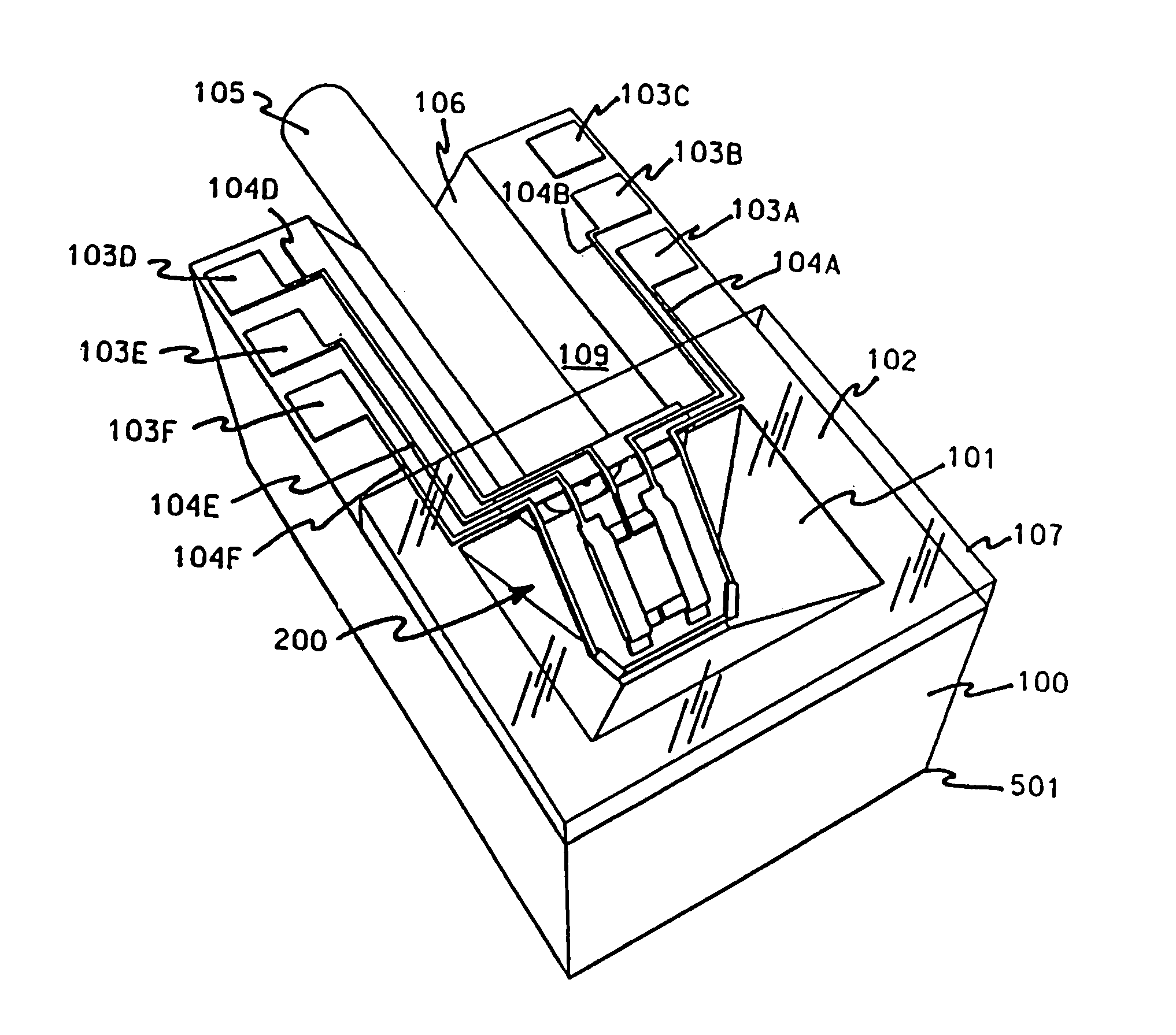
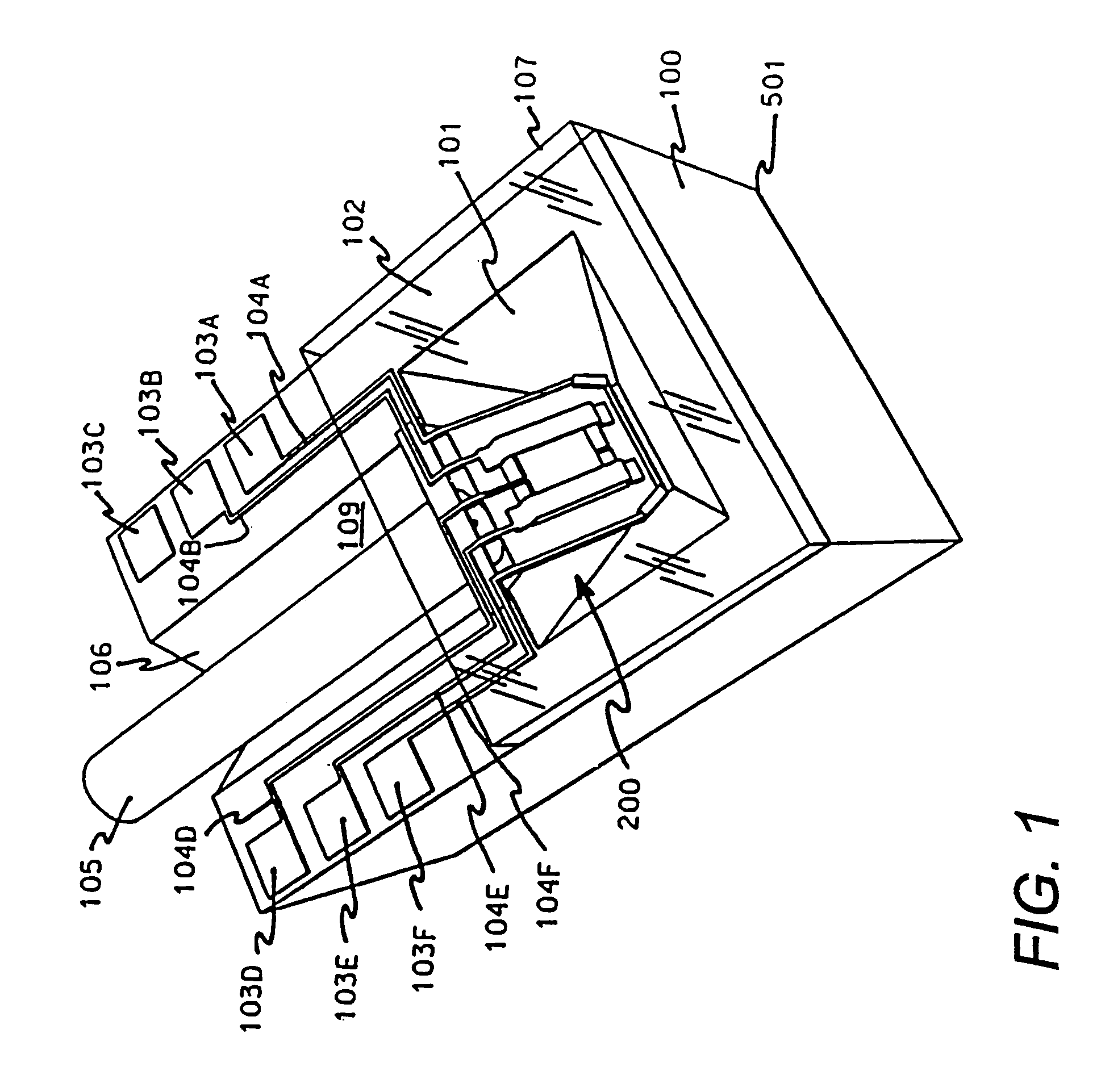
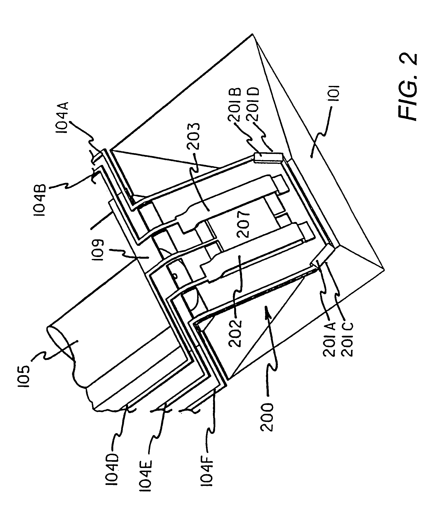
[0040]Referring now to FIGS. 1, 2 and 6 a first aspect of the present invention provides a precision micromachined V-groove 106 into which an optical fiber 105 is cemented or otherwise affixed. A light wave propagating through optical fiber 105 is emitted from the core in the direction of micromirror assembly 200. The surface normal of micromirror assembly 200 is given a precise angle 508 and locked in place with the activation of solder bars 201A and 201B. For the configuration shown, angle 508 has a value of 45 degrees with respect to optical axis 507 as shown in FIG. 6. Upon striking the underside of submirror 207, the light wave is reflected downward through body 100 of the device. Electrodes 202 and 203 are in close proximity to submirror 207 and when a voltage potential is disproportionately introduced on one or the other electrode with respect to grounded submirror 207, an unbalanced electrostatic force is generated.

[0041]The net effect of this force is to rotate submirror 20...


PUM

PropertyMeasurementUnit
Currentaaaaaaaaaa
Electrical conductoraaaaaaaaaa
Electric potential / voltageaaaaaaaaaa

Abstract

An apparatus for precisely steering a beam of light by making use of a hybrid inter optical alignment that occurs when a beam steering mechanism is micro-machined with respect to a crystallographic orientation of a substrate.

Description

[0001]This is a continuation application of U.S. patent application Ser. No. 09 / 695,505, filed Oct. 24, 2000 now abandoned, which is a continuation of U.S. patent application Ser. No. 9 / 192,127, now U.S. Pat. No. 6,137,926, which is a continuation of U.S. patent application Ser. No. 08 / 695,717, now U.S. Pat. No. 5,872,880 filed on Aug. 12, 1996.BACKGROUND[0002]The field of the present invention relates, in general, to methods and devices for manipulating and steering beams of light. More specifically, the field of the invention relates to a compact, hybrid system of optical components that accept a beam of light from an optical element or fiber, steer the beam in one or more directions, and pass the deflected beam into open space or through a secondary optical element or fiber.[0003]Investigators of optical phenomenon typically rely on massive, vibration damped optical benches to maintain precise alignment between optical elements during prototyping. Optical elements might consist o...

Claims


Application Information

Patent Timeline
IPC IPC(8): G02B6/42G02B6/12G02B6/35G02B6/36G02B26/08G02B26/10G11B7/085
CPCG02B6/4214G02B6/4226G02B26/0841G02B26/101G02B6/3518G02B6/3594G02B6/3652G02B6/3692G02B2006/12104G11B7/08564
Inventor MAYNARD, RONALD S.
Owner MAYNARD RONALD S
Why Eureka
Try Eureka