
Insulation and reinforcement of individual bonding wires in integrated circuit packages

a technology of integrated circuits and bonding wires, which is applied in the direction of electrical equipment, semiconductor devices, semiconductor/solid-state device details, etc., can solve the problems of short circuits, decrease in package yield, and decrease in the performance of the resulting packaged integrated circuit, so as to reduce the likelihood and intensity of inductive coupling and/or crosstalk interference, reduce the likelihood and intensity of short rejects, and enhance the structural rigidity of the bonding wires

Active Publication Date: 2007-04-10
NAT SEMICON CORP
View PDF14 Cites 14 Cited by
  • Summary
  • Abstract
  • Description
  • Claims
  • Application Information

AI Technical Summary

Benefits of technology

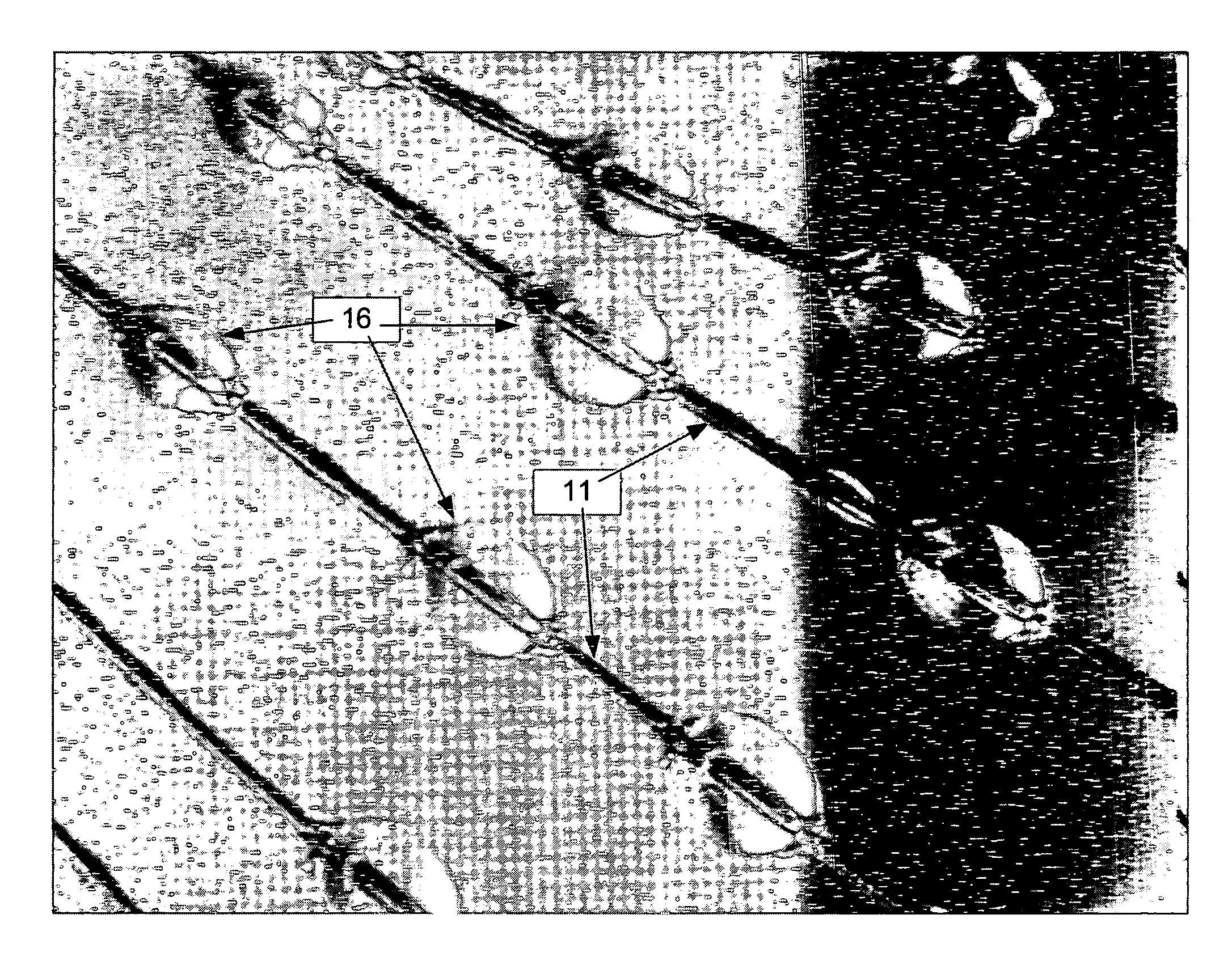
[0004]To achieve the foregoing and other objects and according to the purpose of the present invention, a method for insulating and reinforcing individual bonding wires in integrated circuit packages is disclosed. In one embodiment, bonding wires are coated with an insulating material prior to the molding process. The insulating coating comprises a coating mixture that is applied to the bonding wires using an airbrush. The method enables assembly of packages with bonding wires exceeding industry specification for wire length (per wire diameter) as well as development of inboard and stacked bonding applications by eliminating mold flow induced short rejects. This is accomplished by: (a) Electrically insulating the bonding wires by coating them with an insulating mixture; (b) physically isolating the bonding wires as a result of bead formation around individual bonding wires, with the insulating beads acting as contact barriers as well as reducing the likelihood and intensity of inductive coupling and / or crosstalk interference between adjacent bonding wires due to proximity of bonding wires; and (c) enhancing the structural rigidity of the bonding wires as a result of the coating.

Problems solved by technology

As a result of wire sweep, some displaced bonding wires may come in contact with other bonding wires and produce short circuits.
Wire sweep generally causes a decrease in package yields, since packages with shorts are rejected (“short rejects”).
This can lead to increased inductive coupling and / or crosstalk interference between adjacent bonding wires, which can decrease the performance of the resulting packaged integrated circuit and lead to further reductions in package yields.

Method used


Image

  • Insulation and reinforcement of individual bonding wires in integrated circuit packages
  • Insulation and reinforcement of individual bonding wires in integrated circuit packages
  • Insulation and reinforcement of individual bonding wires in integrated circuit packages

Examples


Embodiment Construction

[0013]Methods for isolation and reinforcement of individual bonding wires in integrated circuit packages are described below. In the following description, numerous specific details are set forth in order to provide a thorough understanding of the present invention. It will be understood, however, by one skilled in the art, that the present invention may be practiced without some or all of these specific details. In other instances, well known process operations have not been described in detail in order not to unnecessarily obscure the present invention.

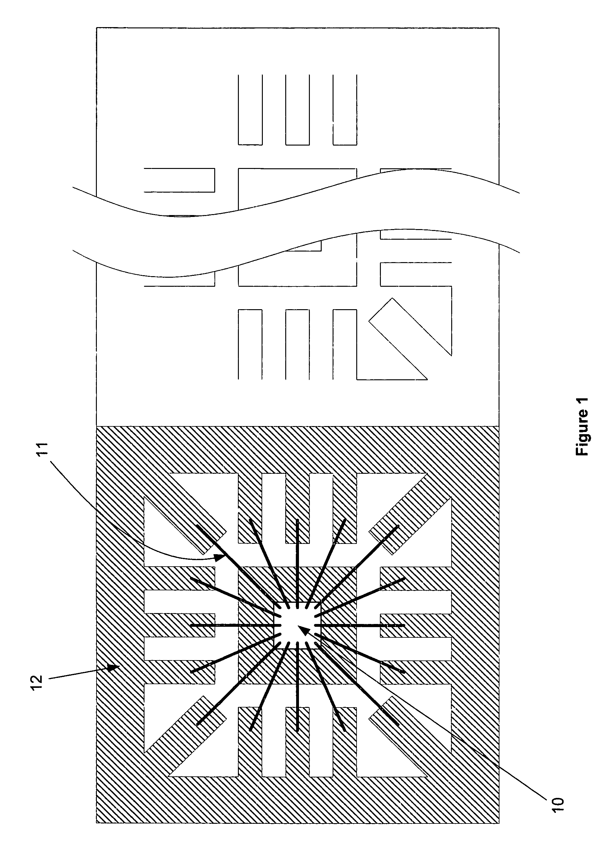
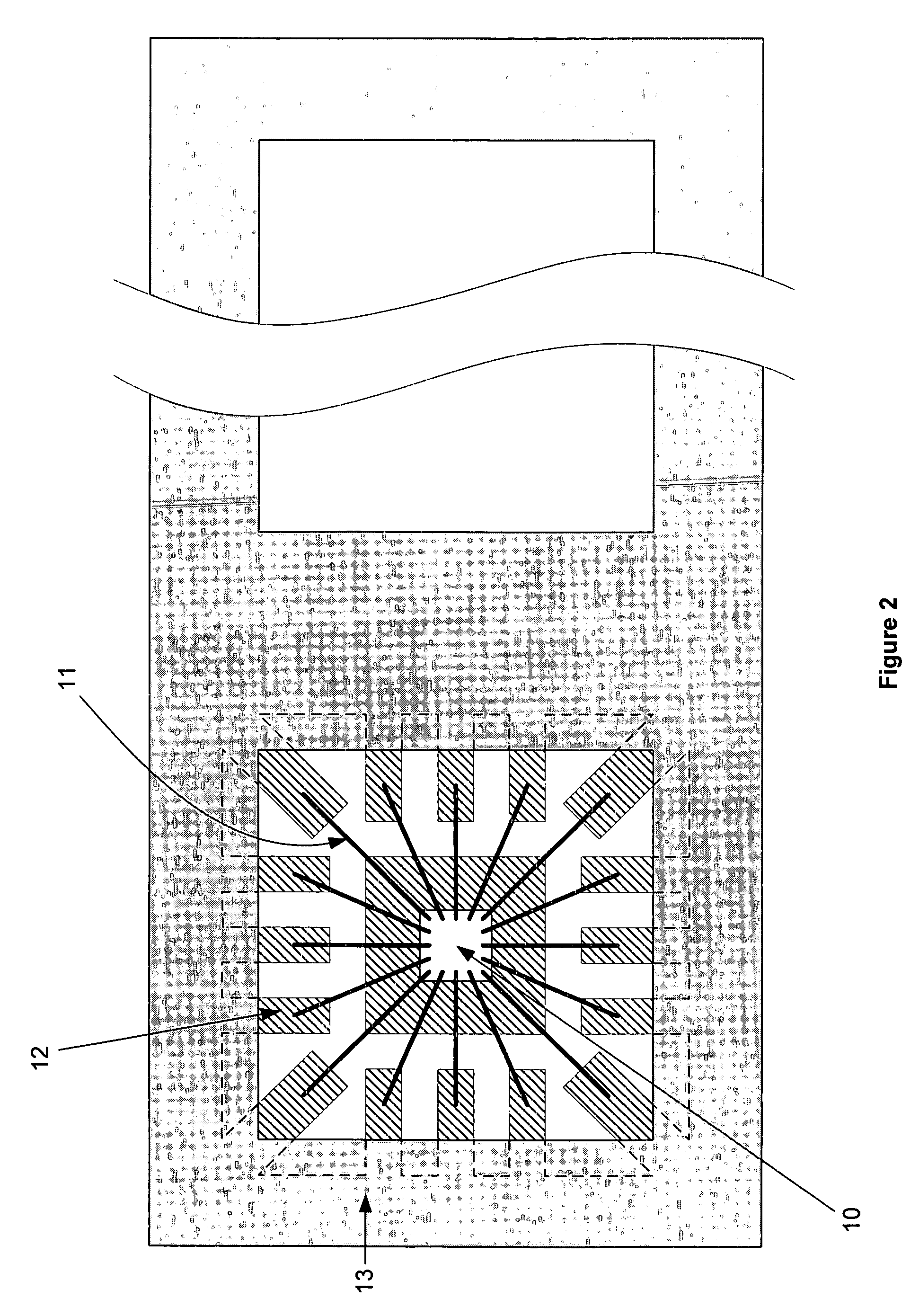
[0014]FIG. 1 is a diagrammatic top view of a wire bonded lead frame 12, in accordance with an embodiment of the present invention. Lead frame 12 is a sheet metal framework upon which an integrated circuit (die) 10 is attached. The die 10 is wire bonded to the lead frame 12 using bonding wires 11, and then molded or otherwise encased using plastic molding, epoxy, ceramic or metallic casing, or other protective material. The result is...


PUM


Abstract

In an integrated circuit package, a method for insulation and reinforcement of individual bonding wires in an integrated circuit package. Using an airbrush, bonding wires are sprayed and coated with an insulating material prior to the molding process. Mold flow induced short rejects are eliminated as a result of: (a) Electrically insulating the bonding wires by coating them with an insulating mixture; (b) Physically isolating the bonding wires as a result of bead formation around individual bonding wires, with the insulating beads acting as contact barriers between the bonding wires; and (c) Enhancing the structural rigidity of the bonding wires as a result of the coating. Reinforcement and separation of bonding wires also reduces inductive coupling and / or crosstalk interference due to proximity of bonding wires.

Description

BACKGROUND OF THE INVENTION[0001]The present invention relates generally to wire bonded integrated circuit packages and, more particularly, to methods and arrangements for isolation and reinforcement of individual bonding wires in integrated circuit packages.[0002]In a wire bonded integrated circuit package, a die is attached and wire bonded to a lead frame (or other substrate) and then molded. During the molding process, the flow of the mold may displace some bonding wires, a phenomenon commonly referred to as “wire sweep”. As a result of wire sweep, some displaced bonding wires may come in contact with other bonding wires and produce short circuits. Wire sweep generally causes a decrease in package yields, since packages with shorts are rejected (“short rejects”). In other situations, wire sweep may push adjacent bonding wires closer together than is desired even though they do not actually touch. This can lead to increased inductive coupling and / or crosstalk interference between ...

Claims


Application Information

Patent Timeline
IPC IPC(8): H01L21/50
CPCH01L21/568H01L21/6835H01L23/4952H01L24/49H01L2224/48091H01L2224/48247H01L2224/4899H01L2224/49171H01L2224/8592H01L2924/01005H01L2924/01082H01L2924/14H01L2924/00014H01L24/48H01L2924/01006H01L2924/01033H01L2924/01076H01L2924/00H01L2224/45099H01L2224/05599
Inventor ZAKHARIAN, DAVIDYAMASHITA, GARY H.BROUSSARD, GARY M.
Owner NAT SEMICON CORP
Learn More