Thermoopic type variable optical attenuator and array type variable optical attentuator using this

Inactive Publication Date: 2007-04-10
SEIKOH GIKEN
View PDF9 Cites 8 Cited by
  • Summary
  • Abstract
  • Description
  • Claims
  • Application Information

AI Technical Summary

Benefits of technology

[0013]It is preferable for the thermo optical variable optical attenuator according to the present invention to provide a triangular shaped auxiliary waveguide disposed in the V-shaped region where one side of the multimode light propagating part of the first optical waveguide and the second optical waveguide disposed in a direction inclined at an angle 2β on one side of that the multimode light propagating part intersect, for efficiently receiving and propagating the high order mode light. By providing a triangular shaped auxiliary waveguide at the multimode light receiving part of a second optical waveguide, high order mode light excited by the heater can be more efficiently taken in. This enables more efficient operation of the above described effect of controlling propagation of excited high order mode light around the multimode light propagating part.
[0014]It is preferable for the other side of the multimode light propagating part to form a notch made by removing a triangle, in order to reduce light propagation loss arising at the multimode light propagating part. By having the other side of the multimode light propagating part of a form of a notch made by removing a triangle, the length of the coupling of one side of the multimode light propagating part of the first optical waveguide and the multimode light receiving part of the second optical waveguide becomes smaller, thus, when current is not flowing to the heater, that is to say, when light attenuation is not required leakage of part of incident light to the multimode light receiving part of the second optical waveguide and attenuation of the incident light can be prevented, enabling an optical attenuator having a broader variable range of light attenuation quantity to be obtained.
[0015]It is preferable for one side of the multimode light propagating part of the first optical waveguide and the multimode light receiving part of the second optical waveguide to be separated having a determined interval therebetween to facilitate optical coupling. By disposing the

Problems solved by technology

Optical amplifiers, (e.g. erbium doped fiber amplifiers: EDFA) are essential for WDM systems, however as optical amplifiers normally have wavelength-dependent gain problems arise in connection with saturation in receiver and a deteriorating S/N ratio.
When an array type variable optical attenuator is configured consisting of a plurality of the above described thermo

Method used


Image

  • Thermoopic type variable optical attenuator and array type variable optical attentuator using this
  • Thermoopic type variable optical attenuator and array type variable optical attentuator using this
  • Thermoopic type variable optical attenuator and array type variable optical attentuator using this

Examples


second embodiment

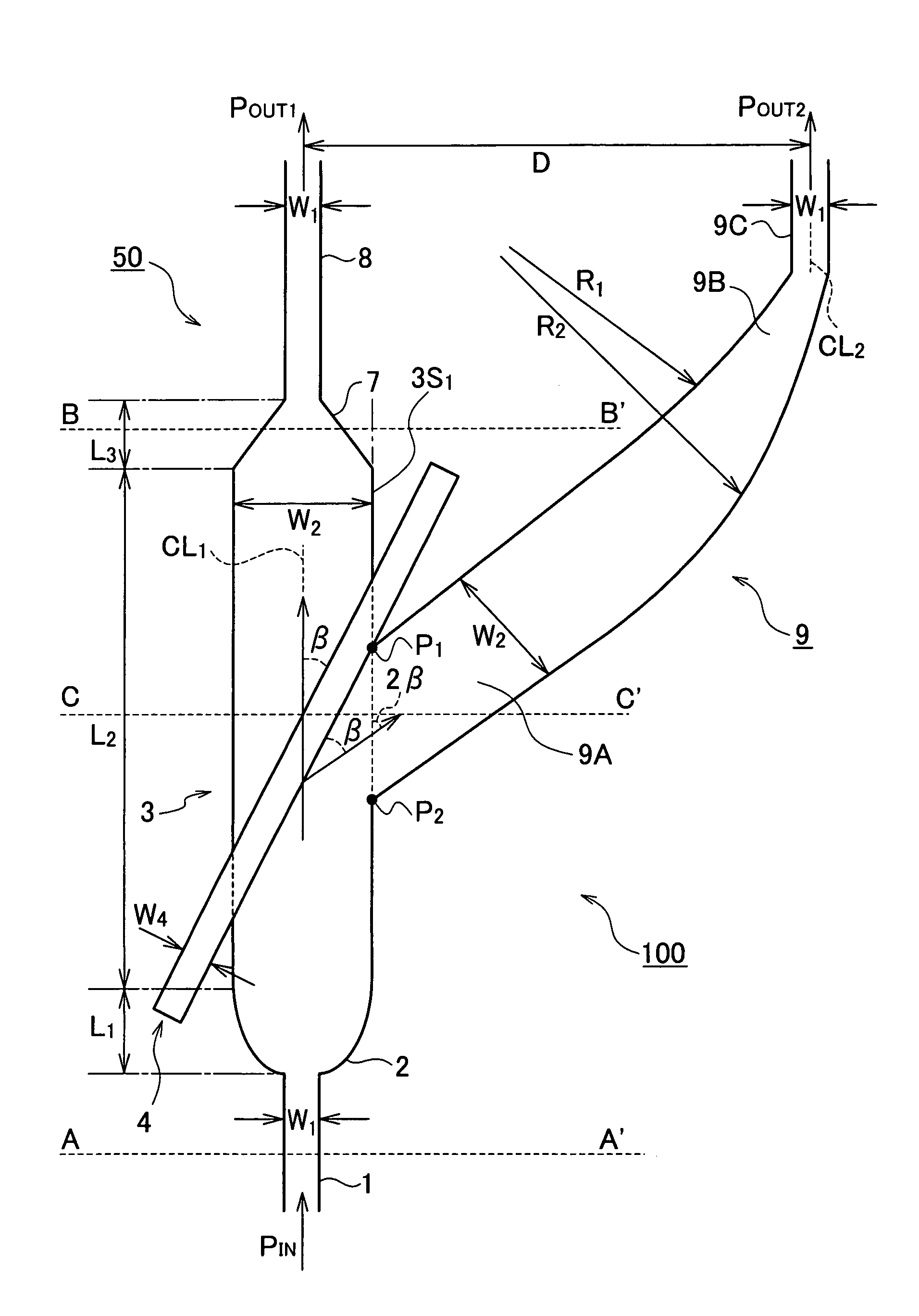
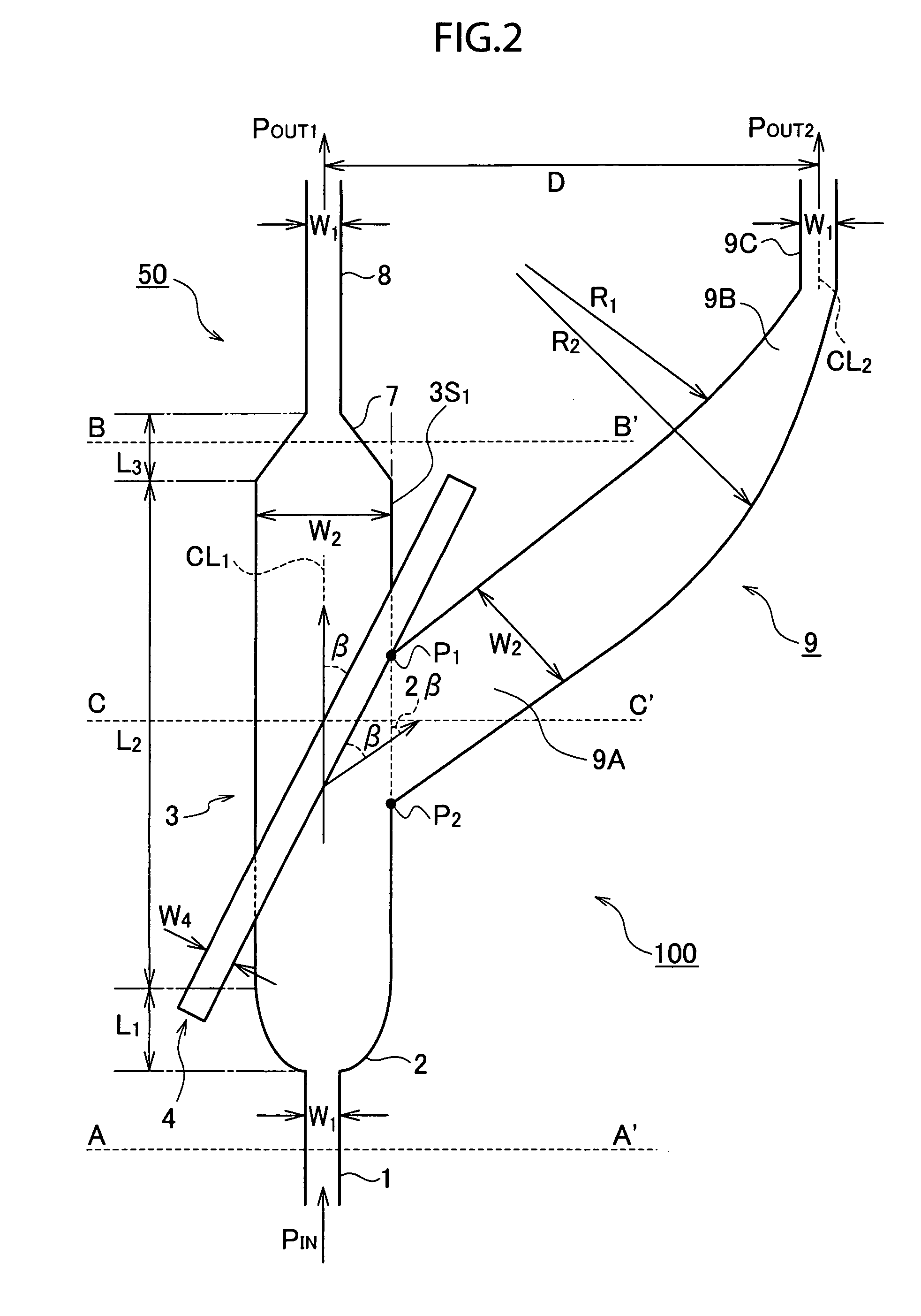
[0048]The thermo optical type variable optical attenuator 100A according to this second embodiment provides an auxiliary optical waveguide 10 for taking in high order mode light excited by the thin film heater layer 4 in the form of a triangular shaped optical waveguide the vertices of which are the V-shaped regions P1, P3 and P4 intersecting with the second optical waveguide 9 that extends in a Y shape from the side face 3S1 of the multimode optical propagating part 3 of the first optical waveguide 50.

[0049]The principles of the operation of this thermo optical type variable optical attenuator 100A according to this second embodiment configured as described above will now be described.

first embodiment

[0050]In the same manner as applies with respect to the operations of the first embodiment, when an electric current flows to the thin film heater 4 the greater part of the high order mode light excited thereby is guided to enter the light receiving part 9A of the second optical waveguide 9, however due to the operation of the Goos-Hanchen effect, a part of this high order mode light is diffused and emitted from the V-shaped region T1 at which the multimode optical propagating part 3 and the second optical waveguide 9 intersect.

[0051]Thus, in the case of this embodiment, the triangular shaped auxiliary optical waveguide 10 is disposed in the V-shaped region T1 comprising the above apex angle 2β, and due to this, high order mode light diffused and emitted from the side face 3S1 of the multimode optical propagating part 3 is able to be taken in more smoothly at the second optical waveguide 9.

[0052]Accordingly, where there is an array type variable optical attenuator configured having ...

third embodiment

[0054]The thermo optical type variable optical attenuator 100B according to this third embodiment provides a waveguide notch T21 made by removing a triangle shaped part the vertices P2, P5 and P6 of which are at the lower part of the light receiving part 9A of the second optical waveguide 9 separated into a Y shape from the side face 3S1 of the multimode optical propagating part 3.

[0055]The operations of this thermo optical variable optical attenuator 100B according to this third embodiment configured as described above will now be described.

[0056]It is when there is no electric current flowing to the thin film heater layer 4 that the operations of this embodiment are most distinguishable and thus the following explanation focuses solely on this condition.

[0057]The optical waveguide 9 for guiding and diffusing and emitting high order mode light excited by the thin film heater 4 is subject to a problem of an increased degree of transmission loss as part of incident light propagating ...


PUM


Abstract

A thermo optical type variable optical attenuator suitable for application in an array type variable optical attenuator that realizes low crosstalk between neighboring waveguides in the array is provided. A thermo optical type variable optical attenuator 100 using optical material having negative optical effect provides a multimode optical propagating part 3 disposed via a tapered part 2 and a tapered part 7 between single mode optical waveguides 1 and 8. A thin-film heater 4 is disposed above the multimode optical propagating part 3 at an angle of inclination β in relation to the direction of light propagation along a first optical waveguide 50. Moreover, a second optical waveguide 9 optically coupled with a side face 3S1 of the multimode optical propagating part 3 is provided at an angle of inclination 2β in relation to the direction of light propagation along the first optical waveguide 50.

Description

TECHNICAL FIELD[0001]The present invention is in the field of high capacity multiple channel optical transmission systems and optical measuring systems and relates specifically to a thermo optical type variable optical attenuator that can adjust the strength of optical signals for each channel and an array type variable optical attenuator that uses this thermal optical type variable optical attenuator.BACKGROUND ART[0002]In recent years, in line with the rapid diffusion of the Internet, as one of the challenges involved with increasing the transmission capacity of optical transmission networks wavelength division multiplexing (WDM) has been achieved in which a plurality of signals having different wavelengths are multiplexed for transmission over a single fiber. Optical amplifiers, (e.g. erbium doped fiber amplifiers: EDFA) are essential for WDM systems, however as optical amplifiers normally have wavelength-dependent gain problems arise in connection with saturation in receiver and...

Claims


Application Information

Patent Timeline
IPC IPC(8): G02B6/26G02B6/42G02F1/01G02F1/313
CPCG02F1/0147G02F1/3137G02F2203/48
Inventor JIANG, XIAOQINGWU, YUYINGWANG, MINGHUALAI, GUANMING
Owner SEIKOH GIKEN
Why Eureka
Try Eureka