Implantable lead-based sensor powered by piezoelectric transformer

a transformer and lead-based technology, applied in piezoelectric/electrostrictive/magnetostrictive devices, piezoelectric/electrostriction/magnetostriction machines, etc., can solve the problems of compromising imd longevity, power efficiency and associated battery consumption, etc., to reduce electromagnetic interference among different sensors, reduce the effect of low profile, and low cos

Inactive Publication Date: 2007-04-10
MEDTRONIC INC
View PDF15 Cites 75 Cited by
  • Summary
  • Abstract
  • Description
  • Claims
  • Application Information

AI Technical Summary

Benefits of technology

[0005]In general, the invention is directed to an IMD having a piezoelectric transformer to power a lead-based sensor. The IMD powers the piezoelectric transformer with a low amplitude signal. The piezoelectric transformer-serves to convert the voltage level of the low amplitude signal to a higher voltage level to drive the sensor. produced by a battery in the IMD to voltage levels appropriate for IMD operation. A piezoelectric transformer offers small size and low profile, as well as operational efficiency, and permits the IMD to transmit a low amplitude signal to a remote sensor deployed within an implantable lead. In addition, the piezoelectric transformer provides electrical isolation that reduces electromagnetic interference among different sensors.

Problems solved by technology

An IMD is typically designed for use over a period of years, and therefore power efficiency and associated battery consumption is a significant concern.
In general, powered sensors contribute to power consumption and battery drain, and can compromise IMD longevity.

Method used


Image

  • Implantable lead-based sensor powered by piezoelectric transformer
  • Implantable lead-based sensor powered by piezoelectric transformer
  • Implantable lead-based sensor powered by piezoelectric transformer

Examples


Embodiment Construction

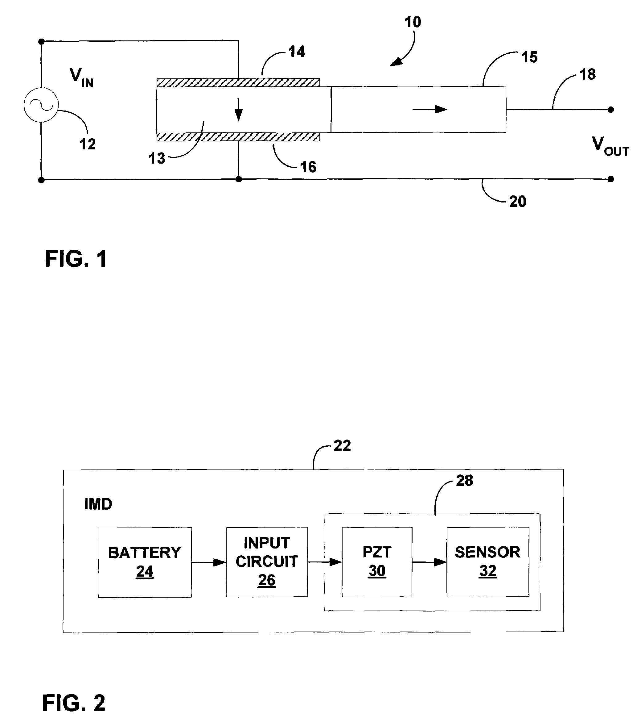
[0018]FIG. 1 is a schematic view illustrating a piezoelectric transformer 10. An input circuit 12 drives piezoelectric transformer 10 with an input signal VIN having a frequency matched approximately to the resonant frequency of piezoelectric transformer 10. Piezoelectric transformer 10 includes a first (input) resonator 13 sandwiched between electrodes 14, 16, and a second (output) resonator 15 having an output 18 that generates an output signal VOUT. A common ground 20 serves as reference for input signal VIN and output signal VOUT.

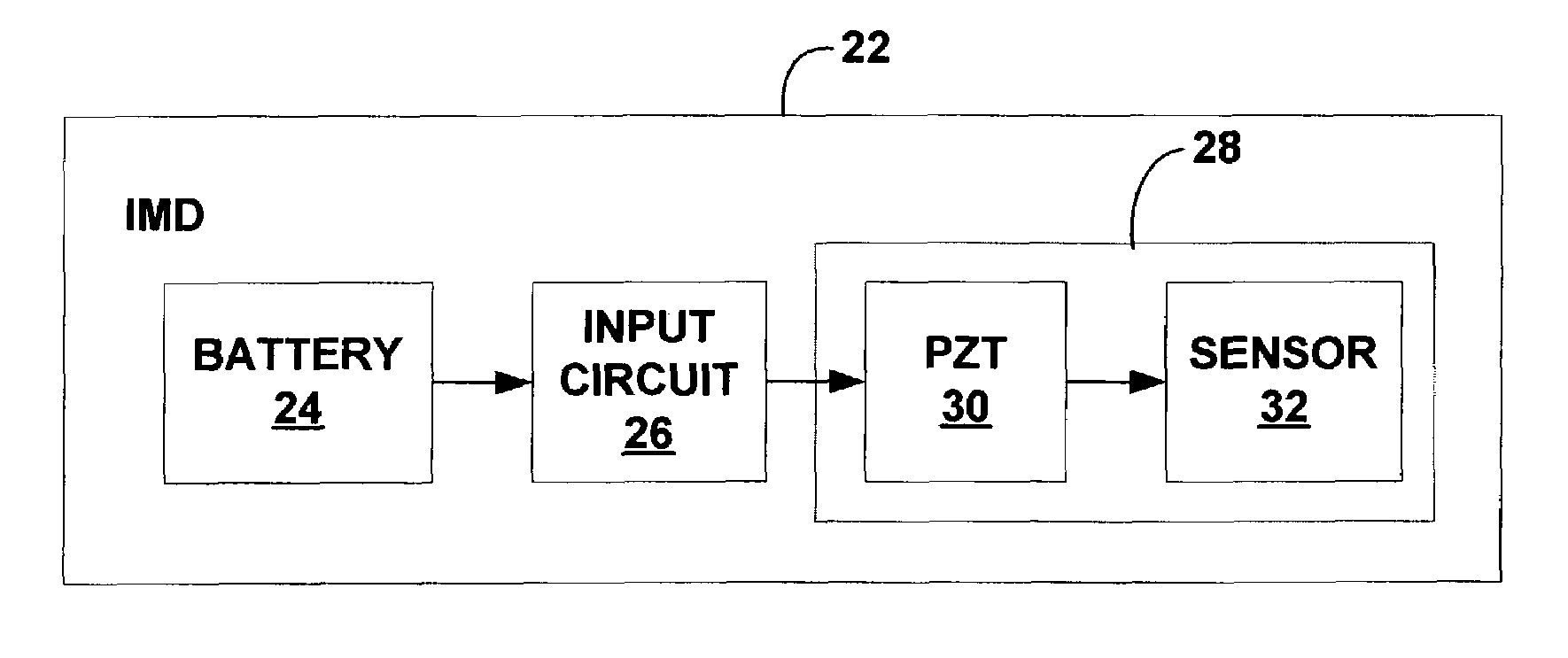
[0019]As described herein, piezoelectric transformer 10 serves to convert a first voltage to a second voltage higher than the first voltage within an IMD. The first voltage is generated with power delivered by a battery within the IMD. The second voltage (VOUT) is applied to support operation of a lead-based sensor, i.e., a sensor carried by an implantable lead associated with the IMD. Examples of powered sensors suitable for use with piezoelectric tran...


PUM


Abstract

In general, the invention is directed to an IMD having a piezoelectric transformer to power a lead-based sensor. The IMD powers the piezoelectric transformer with a low amplitude signal. The piezoelectric transformer serves to convert the voltage level of the low amplitude signal to a higher voltage level to drive the sensor produced by a battery in the IMD to voltage levels appropriate for IMD operation. A piezoelectric transformer offers small size and low profile, as well as operational efficiency, and permits the IMD to transmit a low amplitude signal to a remote sensor deployed within an implantable lead. In addition, the piezoelectric transformer provides electrical isolation that reduces electromagnetic interference among different sensors.

Description

FIELD OF THE INVENTION[0001]The invention relates to implantable medical devices and, more particularly, to implantable medical devices that include lead-based sensors.BACKGROUND OF THE INVENTION[0002]Implantable medical devices (IMDs), such as implantable cardiac pacemakers, pacemaker-cardioverter-defibrillators, neurostimulators, gastric stimulators, drug pumps, loop recorders, and the like, generally make use of battery power to support the output and functionality of such devices. An IMD is typically designed for use over a period of years, and therefore power efficiency and associated battery consumption is a significant concern.[0003]Some IMDs receive signals from sensors carried by implantable leads. A sensor may be responsive to a sensed condition in the body, such as electrical activity, blood pressure, blood chemistry or a mechanical property. Sensors responsive to sensed conditions may detect or measure a quantity of clinical significance. Some sensors require power to su...

Claims


Application Information

Patent Timeline
Patent Type & Authority Patents(United States)
IPC IPC(8): A61N1/00A61N1/08A61N1/365
CPCA61N1/08A61N1/36542
Inventor HOUBEN, RICHARD P. M.CHRISTOPHERSON, MARK A.DONDERS, ADRIANUS P.LEINDERS, ROBERTDENO, CURTIS D.
Owner MEDTRONIC INC
Why Eureka
Try Eureka