Side brush

a side brush and bristle technology, applied in the field of side brushes, can solve the problems of inconvenient manufacture of the brush, inability to economically support the dismounting of the bristles from the base element, and insufficient functionality of the current cassette principle, so as to improve the existing state, simple manufacturing process, and simple effect of manufacturing and construction

Inactive Publication Date: 2007-04-17
SAJAKORPI
View PDF8 Cites 10 Cited by
  • Summary
  • Abstract
  • Description
  • Claims
  • Application Information

AI Technical Summary

Benefits of technology

[0007]It is an object of a side brush according to the present invention to provide a decisive improvement regarding the above-discussed problems and thus to raise substantially the existing state of the art. In order to accomplish this object, a side brush of the invention is principally characterized in that the coupling system is implemented by means of elongated channels disposed in the base element in a substantially radial direction and extending through the base element, opening all the way to the edge thereof, which enable coupling the bristle segments immovably to the engagement with the body of a sweeping machine by means of the base element with fasteners interconnecting the same, such as by effecting the attachment in a screw clamping or suchlike fashion.
[0008]Among the most important benefits gained by a side brush of the invention should be mentioned the simplicity and efficiency of its manufacture and construction, by virtue of which there is provided an extremely simple manufacturing process and an extremely user friendly installation and replacement of side brushes. In a preferred embodiment, the inventive side brush is provided with bristle segments whose frame members are manufactured from plastics in which the bristles of a bristle segment are secured at one end thereof in a totally fixed manner. In this respect, it is further possible to manufacture the frame members of bristle segments in a first aspect from a fusion produced from the ends of the bristles. Another possibility is naturally to manufacture the frame members from moulded plastics, in which the bristles of a bristle segment are anchored by one end thereof during its solidification, or else from e.g. a chemically solidifying two-component material, such as polyurethane, epoxy or the like.
[0009]By virtue of the invention, it is thus possible to manufacture an entirely plastic-structured side brush, which in this context is further modifiable by compiling the bristle formations of its bristle segments for example from plastic bristles of thicknesses substantially different from each other, which are capable of replacing steel bristles used in traditional solutions. By virtue of the foregoing, the inherently reusable and, on the other hand and if necessary, also recyclable base element, being preferably a totally planar and substantially uniform thickness plate or disc assembly, further minimizes space demand with regard to a sweeping machine, as well as ensures a reliable operation of the side brush during rotation for a total elimination of rotational asymmetry, which is characteristic of traditional solutions. Another essential benefit gained by a side brush of the invention relates to its applicability in connection with presently available sweeping machines without any necessary modifications.

Problems solved by technology

A downside in this type of solution is particularly the inconvenience of its manufacture, since, first of all, a multitude of paired holes must be drilled in the base element, whereafter the bristles threaded therein must be further clamped in position by means of a back cover.
Another notable drawback is that a side brush of the above type is a disposable item, because dismounting bristles from a base element is not economically viable but, instead, replacing the entire side brush with a new one is more convenient.
This type of solutions, based on a so-called cassette principle, are not currently very functional either, firstly due to the fact that the fabrication of bristle segments is laborious and expensive because, first of all, the positioning of bristles in place requires an unacceptable amount of manual labour, in addition to which the bristles must, on the other hand, be manufactured with a quite high dimensional precision in order to fit the same in a respective coupling system by applying a force as little as possible.
In practice, however, this causes all sorts of problems in an installation process because of rather large manufacturing tolerances existing in this type of construction for natural reasons.
On the other hand, solutions of the above type do not enable recycling or the reuse of bristle segments included therein without unacceptably laborious / expensive dismounting operations, which is why it is generally necessary to ultimately discard such material to a waste disposal site.
In addition, as a result of metal constructions used in association with arrangements of the above type, the base structures of bristle segments become unacceptably massive, wherefor the coupling and bracing systems included in a sweeping machine must also be of a highly robust design.
A problem with this type of solution lies particularly in the fact that there is no way of providing a sufficiently reliable clamping for the bristle segments, since no actual locking can be implemented in this discussed solution.
For this reason, the positions of bristle segments are also somewhat unstable in the vertical axis brush, firstly as a result of manufacturing tolerances in the bristle segments' U-shape and secondly because the clamps included in the plate or disc are subject to bending in extended use.
Thus, in practice, it is not possible to assemble a sufficiently reliable side brush with the discussed type of solution.

Method used


Image

  • Side brush
  • Side brush
  • Side brush

Examples


Embodiment Construction

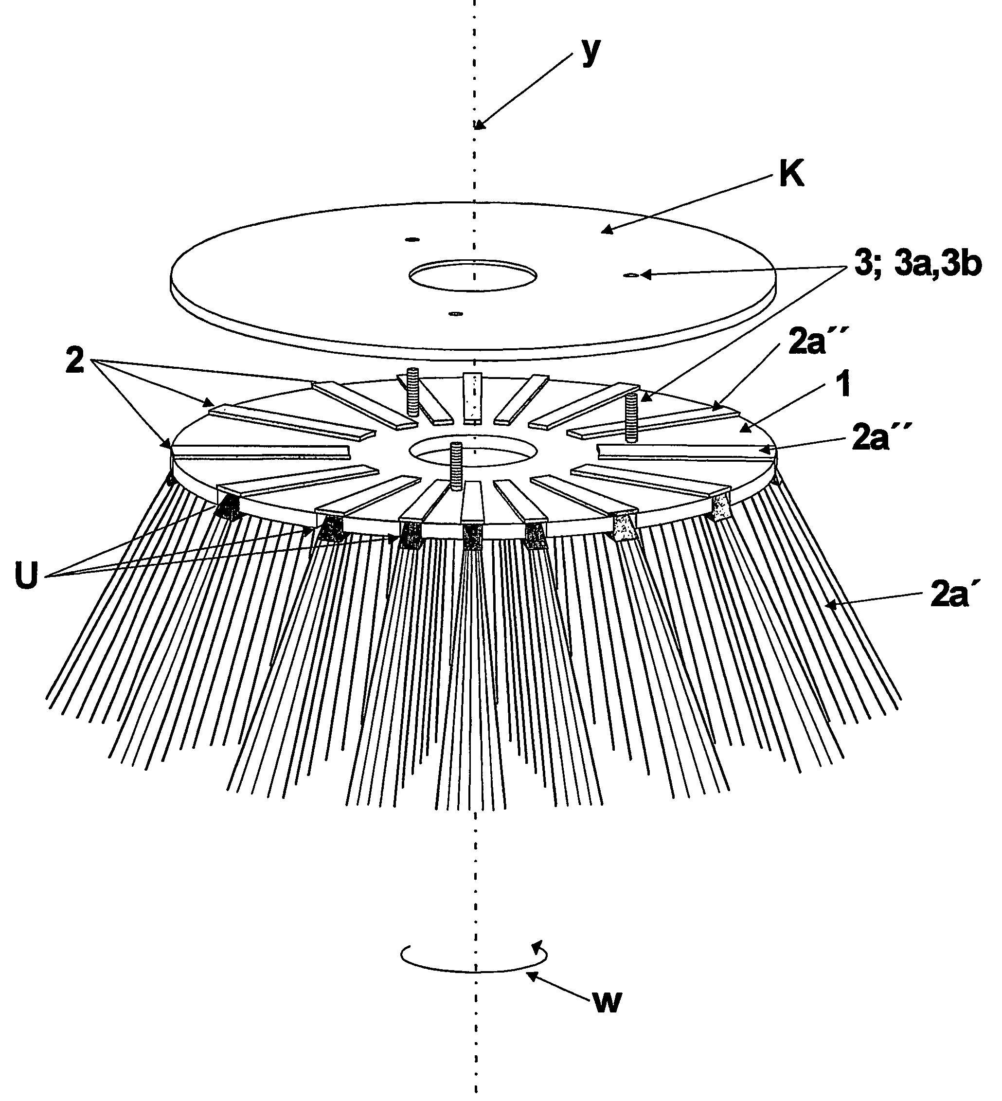
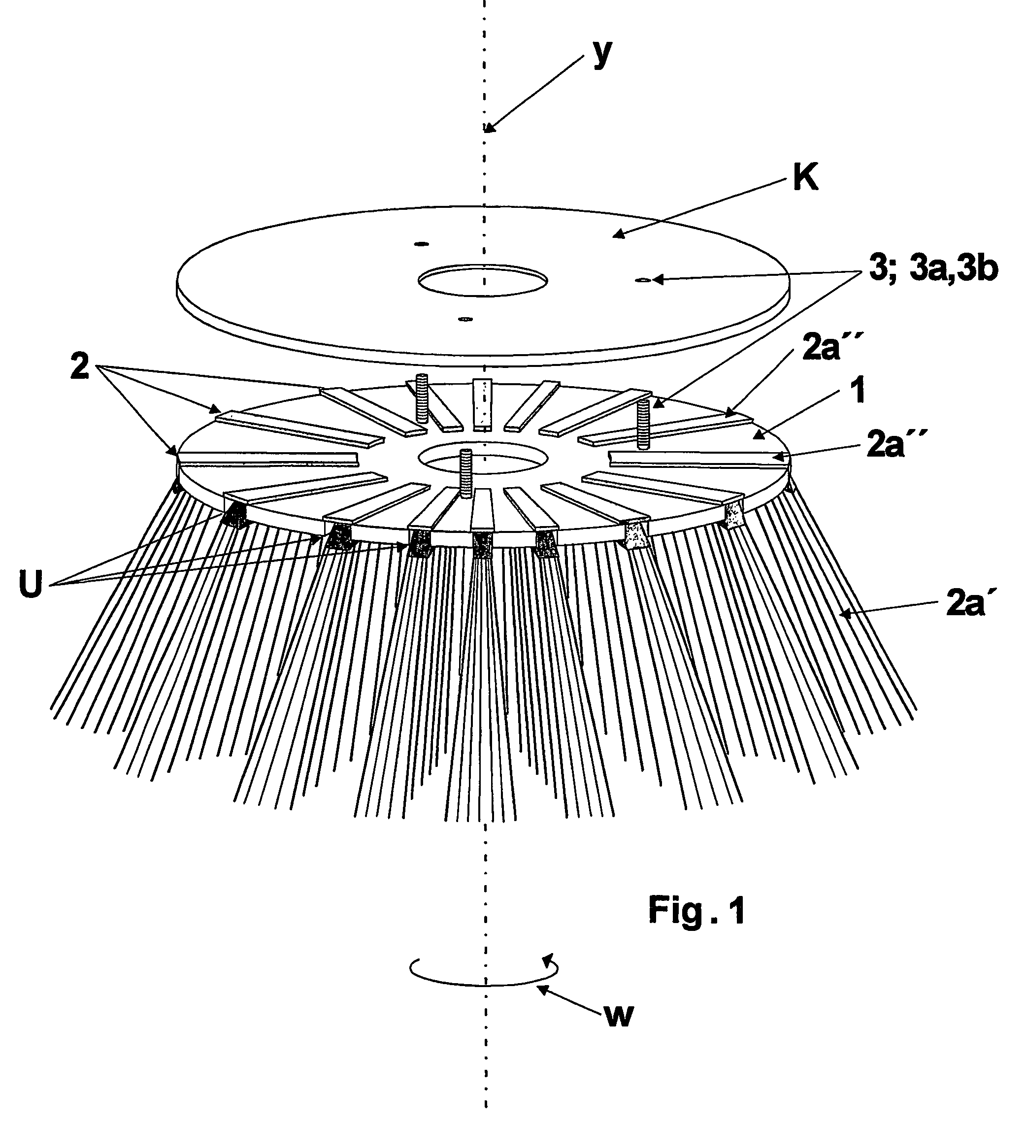
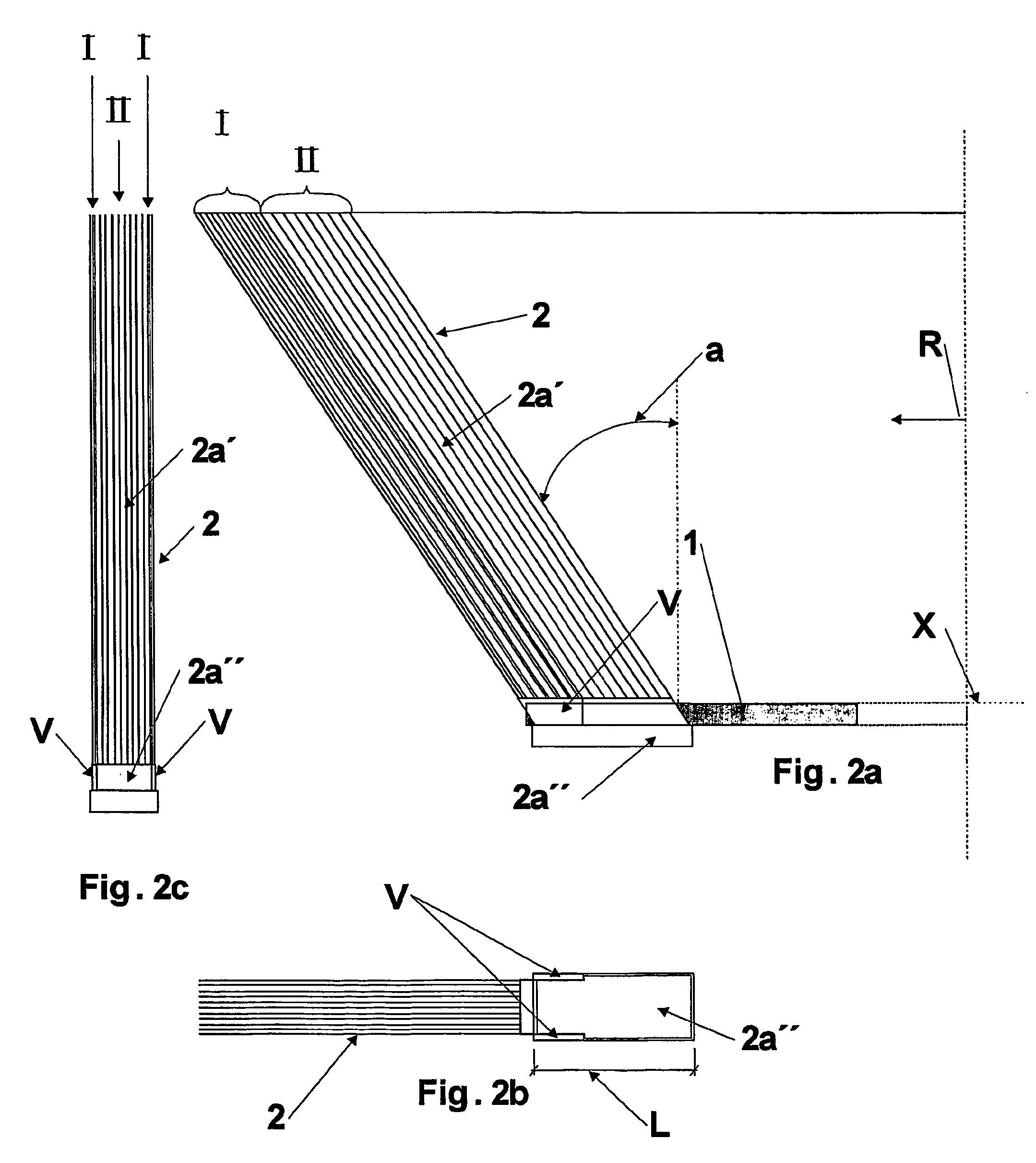
[0019]The invention relates to a side brush, which is adapted to be mounted on the body of a sweeping machine, for use as a brush rotatable w about a rotation axis y, and which comprises a base element 1 and a plurality of individual bristle segments 2 detachably mountable thereto, having bristles 2a′ included therein integrated for a solid unit with a frame member 2a″ joining the same. The base element 1 comprises a substantially planar disc assembly which is provided integrally with a coupling system for coupling the bristle segments 2 therewith on a snap fit principle. The coupling system is implemented by means of elongated channels U disposed in the base element 1 in a substantially radial direction R and extending through the base element, opening all the way to the edge thereof, which enable coupling the bristle segments 2 immovably to the engagement with the body of a sweeping machine by means of the base element 1 with fasteners 3 interconnecting the same, such as in a scre...


PUM


Abstract

A side brush, which is adapted to be mounted on the body of a sweeping machine, for use as a brush rotatable about a rotation axis, and which includes a base and a plurality of individual bristle segments detachably mountable thereto, having bristles included therein integrated for a solid unit with a frame member joining the same. The base includes a substantially planar disc assembly which is provided integrally with a coupling system for coupling the bristle segments therewith on a snap fit principle. The coupling system includes elongated channels disposed in the base in a substantially radial direction and extending through the base, opening all the way to the edge thereof, which enable coupling the bristle segments immovably to the engagement with the body of a sweeping machine by means of the base with fasteners interconnecting the same.

Description

CROSS-REFERENCE TO RELATED APPLICATIONS[0001]This application claims priority to Finnish patent application 20030502 filed 3 Apr. 2003 and is the national phase under 35 U.S.C. §371 of PCT / FI2004 / 000003.FIELD OF THE INVENTION [0002]The invention relates to a side brush, which is adapted to be mounted on the body of a sweeping machine, for use as a brush rotatable about a rotation axis, and which comprises a base element and a plurality of individual bristle segments detachably mountable thereto, having bristles included therein integrated for a solid unit with a frame member joining the same. The base element comprises a substantially planar disc assembly which is provided integrally with a coupling system for coupling the bristle segments therewith on a snap fit principle.BACKGROUND OF THE INVENTION[0003]Side brushes of the above type have been traditionally constructed by means of a base element, made for example from a flat plywood panel and having a radially sufficiently wide zo...

Claims


Application Information

Patent Timeline
IPC IPC(8): E01H1/04A46BA46B7/04A46B7/08A46B13/00A46B13/02
CPCA46B7/04A46B7/08A46B13/005A46B13/008
Inventor KUIVIKKO, REIJOSAJAKORPI, KIMMO
Owner SAJAKORPI
Why Eureka
Try Eureka