Lever device for hydraulic operation

Inactive Publication Date: 2007-04-17
HONDA MOTOR CO LTD
View PDF9 Cites 31 Cited by
  • Summary
  • Abstract
  • Description
  • Claims
  • Application Information

AI Technical Summary

Benefits of technology

[0013]According to the present invention, the knocker member is provided separate from the lever. The knocker member is rotatable independently of the rotational of the lever, and is formed separately from the adjuster. Thus, even when an adjustment of the adjuster is made, the path of rotational of the knocker member does not change, preventing the influence of the adjuster on the operation of the pushrod and the piston. Further, the coupling between the pushrod and the knocker member is maintained even when the lever is rotated by receiving an excessive load in a frontward direction. Still further, since the pushrod and the knocker member need not be coupled with each other by caulking as seen in the conventional lever device, it is easy to assemble the lever device.
[0014]According to the present invention, a stopper is provided which limits the return position of the knocker member. Thus, a rotational of the knocker member in its returning direction to a degree beyond necessity can be inhibited, further ensuring the maintenance of the coupling between the knocker member and the pushrod.
[0015]According to the present invention, the knocker member and the lever are supported on the same rotational axis, simplifying the structure of the lever device, as well as facilitating the assembling of the lever device.
[0016]According to the present invention, the pivotal portion of the knocker member is interposed between the two segments of the pivotal portion of the lever that are separated in the direction of the rotationalal axis, thereby preventing a deformation of the pivotal portion of the knocker member by means of the pivotal portion of the lever. Thus, a sufficient rigidity of the knocker member can be maintained even when a further weight saving of the knocker member is realized.
[0017]According to the present invention, since the elastic member is disposed between the lever and the hydraulic cylinder, while the lever device is in a normal state where a rider's hand is off the lever, the lever is returned to its neutral position by being rotationalally biased by the elastic member in the direction to generate pressure in the hydraulic cylinder to hold the knocker member in contact with the pushrod, as well as to prevent the lever and the knocker member from wobbling.

Problems solved by technology

However, with a change in the amount of projection, a path of a turn of the end changes, which undesirably changes an operation stroke of the pushrod.

Method used


Image

  • Lever device for hydraulic operation
  • Lever device for hydraulic operation
  • Lever device for hydraulic operation

Examples


first embodiment

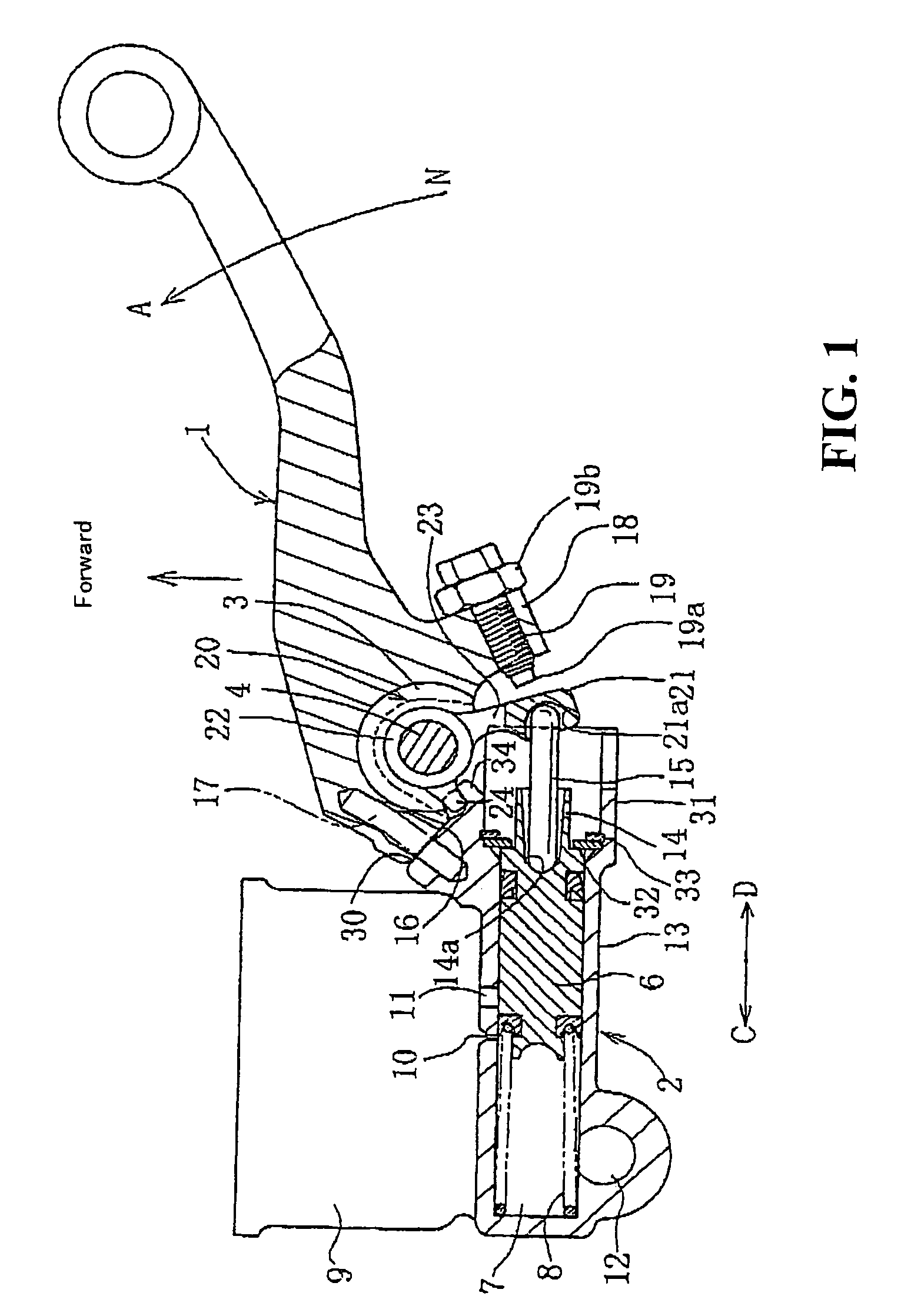
[0037]Hereinafter, preferred embodiments will be described based on the drawings. FIGS. 1 to 5 show a first embodiment applied to a structure of a brake operating lever for a hydraulic brake of a motorcycle. The parts identical with those of the above-described conventional lever device will be denoted by the same reference numerals.

[0038]FIG. 1 is a cross-sectional view of a lever 1 attached to a right-hand side of a handlebar for a motorcycle (see FIG. 8). By operating the lever 1, hydraulic pressure is generated in a master cylinder 2 of a front brake.

[0039]The lever 1 is supported at its base portion 3 by a rotational shaft 4 to be pivotable around the rotationalal shaft 4 relatively to a lever holder 5 formed integrally with the master cylinder 2. In FIG. 1, a bidirectional arrow A-B indicates a direction of rotational of the lever 1. The direction A indicates a direction to return the lever 1 to its original position (a direction to release hydraulic pressure), while the direc...

second embodiment

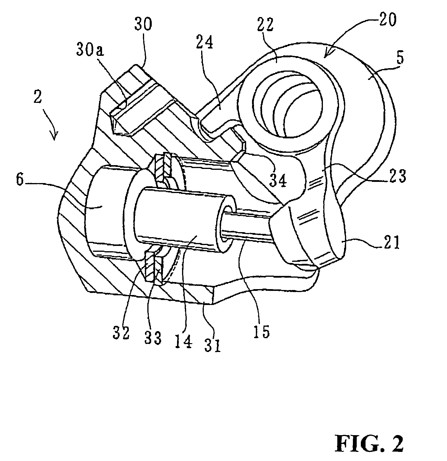
[0064]By the arrangement of the second embodiment, a path of rotation of the knocker member 20 is differentiated from that of the lever 1, so that a path suitable for the operation of the pushrod 15 can be employed. Further, since the order of attaching the knocker member 20 to the base portion 3, and an object to which the knocker member 20 is attached, can be changed. For instance, the knocker member 20 may be attached to an external side of the base portion 3 and the lever holder 5.

[0065]In addition, since the cap 51 which is a separately formed member is used in the knocker portion 21, an accommodating portion for accommodating the pushrod 15 can be easily formed by providing the through-hole 52 in the form of a straight hole of a relatively large diameter capable of allowing the sway of the pushrod 15, and attaching thereto the cap 51 having a spherical recess 53, by caulking or otherwise.

[0066]Further, by forming the cap 51 with a material having an excellent wear resistance, ...

fourth embodiment

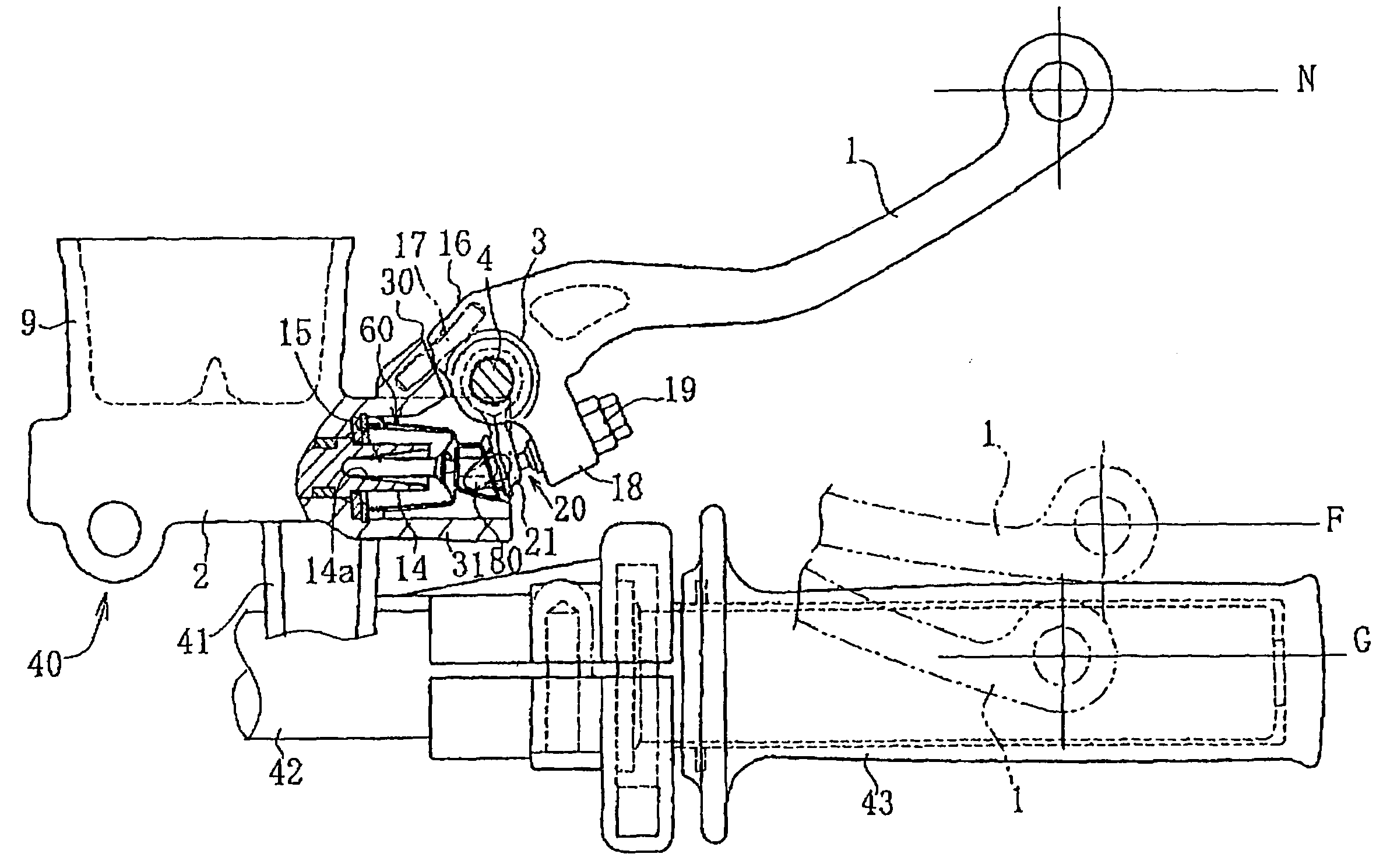
[0069]Referring now to FIGS. 8–16, there will be described the invention. This embodiment is different from each of the above-described embodiments in that the knocker portion has a mechanism for preventing disengagement of the pushrod (including coming off thereof), and there is provided a knocker boot. The parts common to this and the above-described embodiments are referred to by the same reference numerals. FIG. 8 corresponds to FIG. 1, and shows a lever unit 40 which is an integration of the lever 1 and the master cylinder 2, and attached to a bar handle 42 for a motorcycle by way of a bolder 41. A grip 43 is disposed at an end portion of the bar handle 42. The lever 1 rotates in two opposite directions A, B from its neutral position N. In the direction A, the lever 1 is rotatable up to a position to have an end of the stopper end 16 and the stopper shoulder 30 in contact with each other. In the direction B, the lever 1 is rotatable up to a position F to contact the grip 43. Re...


PUM


Abstract

In a lever device for a hydraulic operation where hydraulic pressure is generated in a master cylinder by rotation of a lever, to make invariable an operation of a pushrod, which operates a piston of the master cylinder by being pushed at one end thereof by an adjuster of the lever, irrespectively of an adjustment of the adjuster. The lever is supported by a rotational shaft to be rotatable around the rotational shaft relative to the master cylinder, while a knocker member separate from the lever is supported to be coaxially rotatable. A knocker portion of the knocker member receives an end of the pushrod, which operates the piston. A positional relationship between the pushrod and the knocker portion is made invariable irrespectively of a change in a distance between the adjuster and the knocker portion by an adjustment of the adjuster.

Description

CROSS-REFERENCE TO RELATED APPLICATIONS[0001]The present non-provisional application claims priority under 35 USC 119 to Japanese Patent Application Nos. 2004-145209 and 2005-125347 filed on May 14, 2004 and Apr. 22, 2005, respectively, the entire contents thereof is hereby incorporated by reference.BACKGROUND OF THE INVENTION[0002]1. Field of the Invention[0003]The present invention relates to a lever device for a hydraulic operation, suitable for use, for example, in a hydraulic brake of a motorcycle.[0004]2. Description of Background Art[0005]A lever device for a hydraulic operation of a hydraulic brake of a motorcycle includes a hydraulic master cylinder attached to a handlebar, and a lever attached to the master cylinder such that the lever is rotatable relatively to the master cylinder. The lever device is constructed such that a pushrod for moving a piston of the master cylinder and an adjuster of the lever are connected by caulking or otherwise, and a rotational of the lever...

Claims


Application Information

Patent Timeline
Patent Type & Authority Patents(United States)
IPC IPC(8): B60T7/08B62L3/02B62L3/00F15B15/20F15B21/00F16D55/08G05G1/04
CPCB62L3/023
Inventor UCHIYAMA, MIKIOGOGO, KAZUHIKO
Owner HONDA MOTOR CO LTD
Why Eureka
Try Eureka