Arrangement for the cooling of thermally highly loaded components

a technology of high-loading components and cooling arrangements, which is applied in the direction of efficient propulsion technologies, machines/engines, light and heating apparatus, etc., can solve the problems of high cost of uneconomical effort for laser drilling of cooling air openings, and high cost of manufacturing combustion chambers

Inactive Publication Date: 2007-04-17
ROLLS ROYCE DEUT LTD & CO KG
View PDF23 Cites 10 Cited by
  • Summary
  • Abstract
  • Description
  • Claims
  • Application Information

AI Technical Summary

Benefits of technology

[0006]In a broad aspect, the present invention provides an arrangement for the supply of thermally highly loaded components of gas turbines with cooling air which can be inexpensively produced with low manufacturing effort.
[0012]The advantages of the present invention are the cost-effective manufacturability also by casting, the evenness of the cooling air film produced, the possibility of varying the cooling air film by appropriate selection of the permeability of the wire mesh, and the isolation between the materials of the wire mesh and the component in connection with the high mechanical and thermal loadability resulting therefrom. The components are cost-effectively producible, in particular by casting, since the formation of the cooling air openings can be incorporated into the casting process.

Problems solved by technology

However, the effort for the laser drilling of the cooling air openings is largely uneconomical in relation to the total costs for the manufacture of the combustion chamber.
As is already known, combustion chambers for aircraft turbine engines are also made from individual segments produced by a casting process and joined by laser welding, but here as well, the fine cooling air openings must be expensively produced by lasering since it is impossible to incorporate their production even into the most advanced precision casting process.

Method used


Image

  • Arrangement for the cooling of thermally highly loaded components
  • Arrangement for the cooling of thermally highly loaded components

Examples


Embodiment Construction

[0006]In a broad aspect, the present invention provides an arrangement for the supply of thermally highly loaded components of gas turbines with cooling air which can be inexpensively produced with low manufacturing effort.

[0007]It is a particular object of the present invention to provide a solution to the above problems by an arrangement designed in accordance with the features described herein. Advantageous embodiments of the present invention will be apparent from the description below.

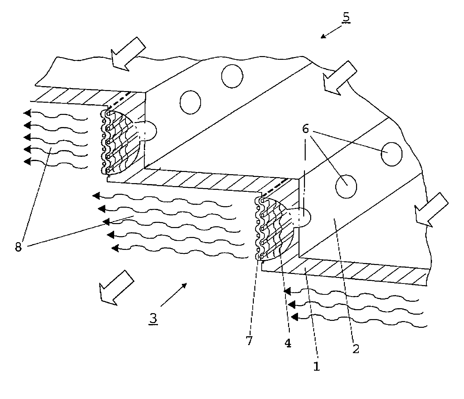
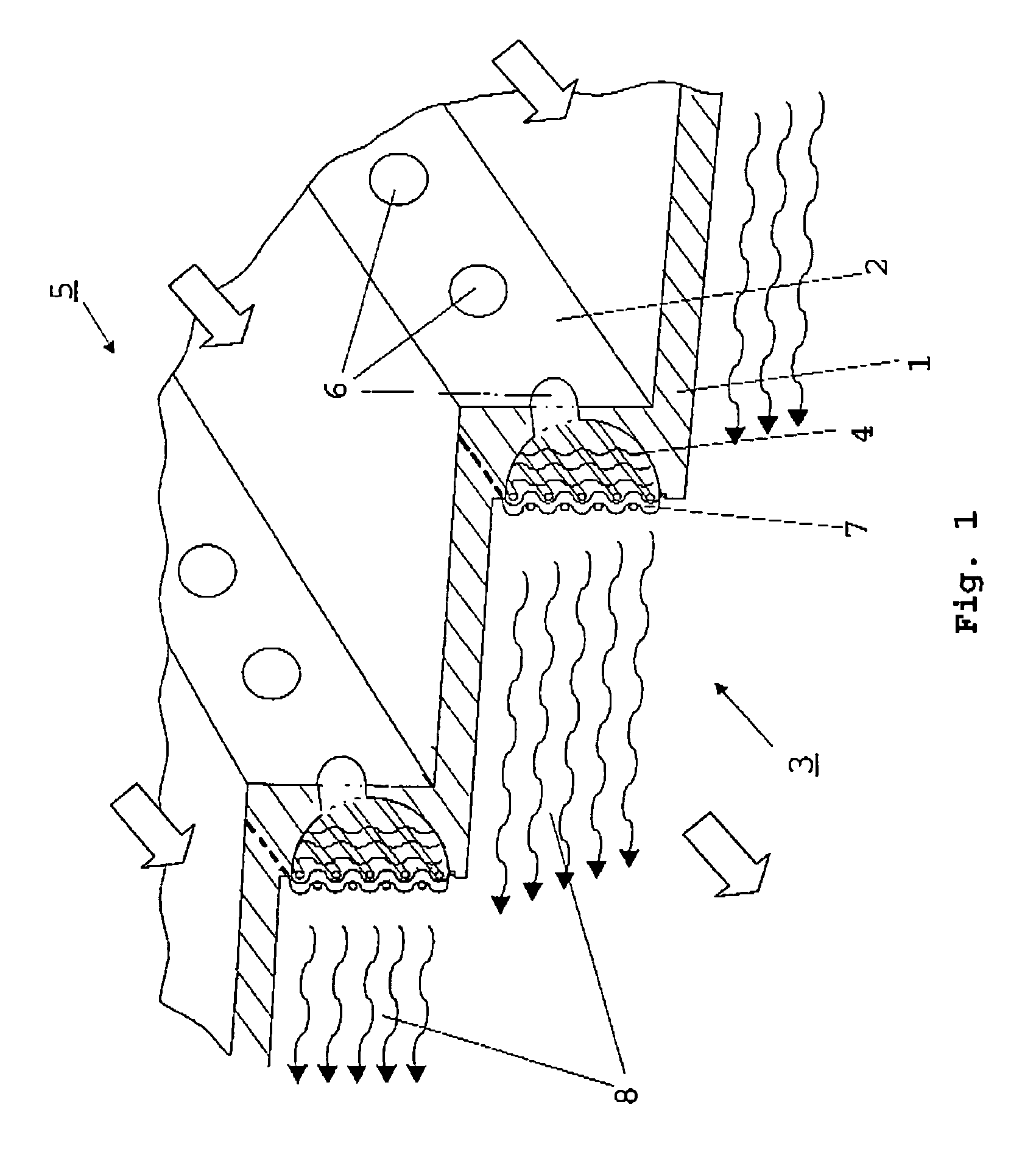
[0008]The general idea of the invention is the formation of at least one cavity in the wall surface to be cooled and shielded against hot gases which is open at the side to be cooled and which connects to cooling air openings for the supply of the required cooling air volume which originate at the opposite wall surface and are producible by casting, while the open side of the cavity is covered by a wire mesh of a certain permeability. The cavity here serves as a pressure accumulator for the contin...


PUM


Abstract

An inexpensively manufacturable arrangement for the cooling of thermally highly loaded components, for example the combustion chamber of a gas turbine, comprises cavities (4) provided on the thermally loaded inner surface / air exit side (3) of the wall (1) of the component which are supplied with a cooling medium from the outer surface / air inlet side (5) via cooling air openings (6) and which are covered by a heat resistant wire mesh (7) of a certain permeability. The cavity, which acts as pressure accumulator, forms, in connection with the wire mesh, a uniform pressurized-air film (8) for the cooling and heat shielding of the wall surface.

Description

[0001]This application claims priority to German Patent Application DE10341515.7 filed Sep. 4, 2003, the entirety of which is incorporated by reference herein.BACKGROUND OF THE INVENTION[0002]This invention relates to an arrangement for the cooling of thermally highly loaded components by means of a cooling medium, and in particular, the cooling of the combustion chamber of gas turbines, in which cooling air openings are provided in the component to be cooled which are supplied with cooling air at an air inlet side to form a cooling air film at the air outlet side of the component.[0003]As is generally known, various components of a gas turbine, for example, the stator vanes and their platforms or the combustion chamber, are cooled with a multitude of minute cooling air openings or slots provided in the wall area, each with a cross-sectional area of approximately 1 mm2, for example. The cooling air which is externally applied to the outer surface of the component also passes the res...

Claims


Application Information

Patent Timeline
Patent Type & Authority Patents(United States)
IPC IPC(8): F02C1/00F02G3/00F23R3/08
CPCF23R3/08F23D2214/00Y02T50/675Y02T50/60
Inventor SCHREIBER, KARL
Owner ROLLS ROYCE DEUT LTD & CO KG
Why Eureka
Try Eureka