Lightweight self-leveling automatic screed apparatus

a self-leveling, automatic technology, applied in the direction of roads, constructions, building constructions, etc., can solve the problems of deflections, variations in the levelness of concrete, and inability to be easily portable or useful on smaller floors

Active Publication Date: 2007-04-17
JACKSON GERALD MCLAIN
View PDF5 Cites 6 Cited by
  • Summary
  • Abstract
  • Description
  • Claims
  • Application Information

AI Technical Summary

Benefits of technology

[0007]It is the object of this invention to provide an apparatus for screeding / striking off concrete with laser accuracy, automatic mechanical means and ease of portability, in which the entire concrete screed process is performed automatically and accurately with minimal assistance from the operator.
[0009]The tripod stance of the present invention provides a lightweight frame which may easily be placed into the fresh concrete, providing a platform from which the screed means may operate to strike off the concrete, with minimal obstruction of the work area, unlike prior art which typically is screeded with the screed means at least partially supported on the fresh concrete. In the present invention the screed means is supported entirely by it's tripod framework, placed into and over the uncured freshly placed concrete.
[0010]Further, the at least three actuator legs, of the present invention, in a triangular stance, advantageously permit maximum access for workers tending the concrete in the work area. The singular rear actuator, provides minimal structural obstruction.

Problems solved by technology

Large, self propelled, laser screeds such as developed by Somero et al., U.S. Pat. No. 4,655,633, are useful for placing huge easily accessible floors, but are not easily portable or useful on smaller floors.
By simply tilting the screed apparatus during placement of the concrete, the result may be deflections and variations in the levelness of the concrete both horizontally and vertically to the operator.

Method used


Image

  • Lightweight self-leveling automatic screed apparatus
  • Lightweight self-leveling automatic screed apparatus
  • Lightweight self-leveling automatic screed apparatus

Examples


Embodiment Construction

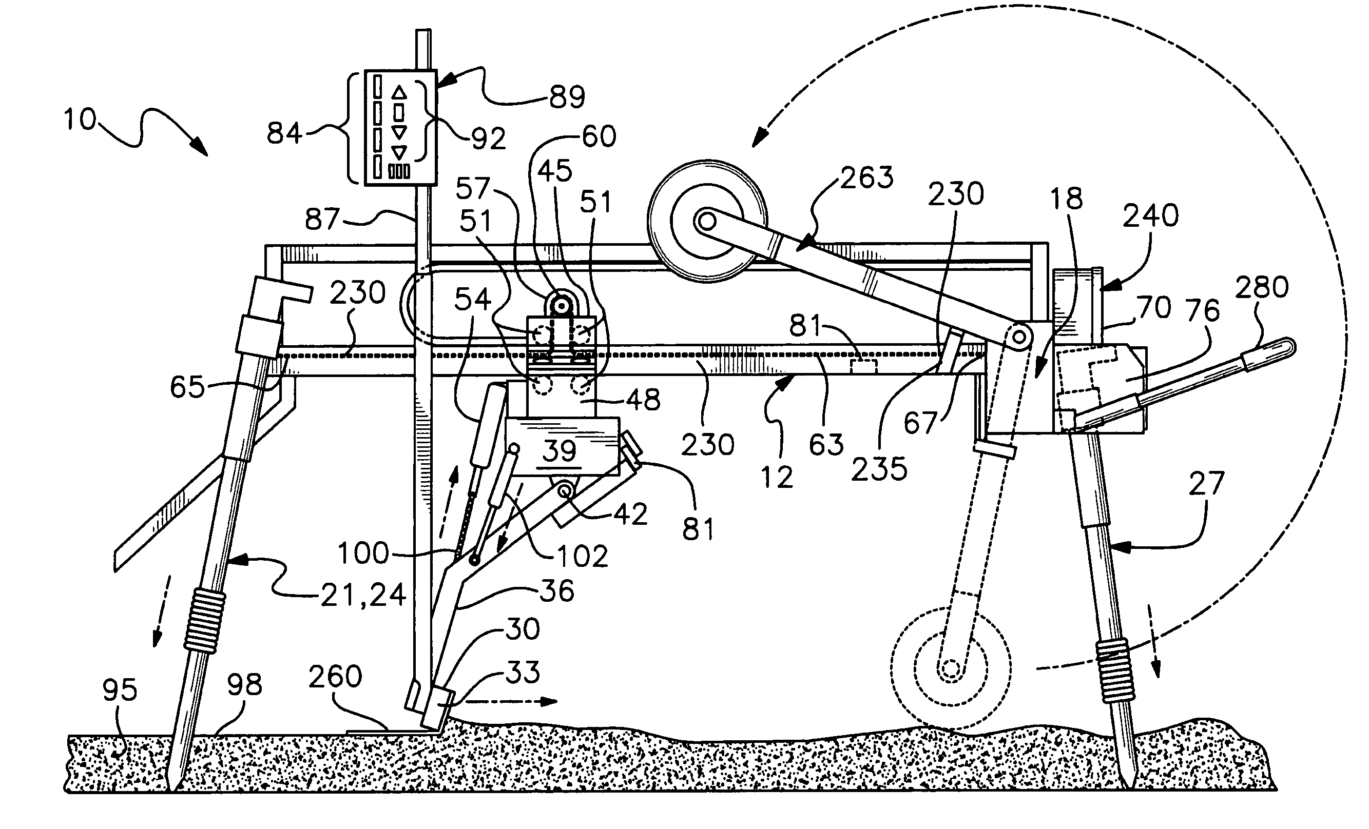
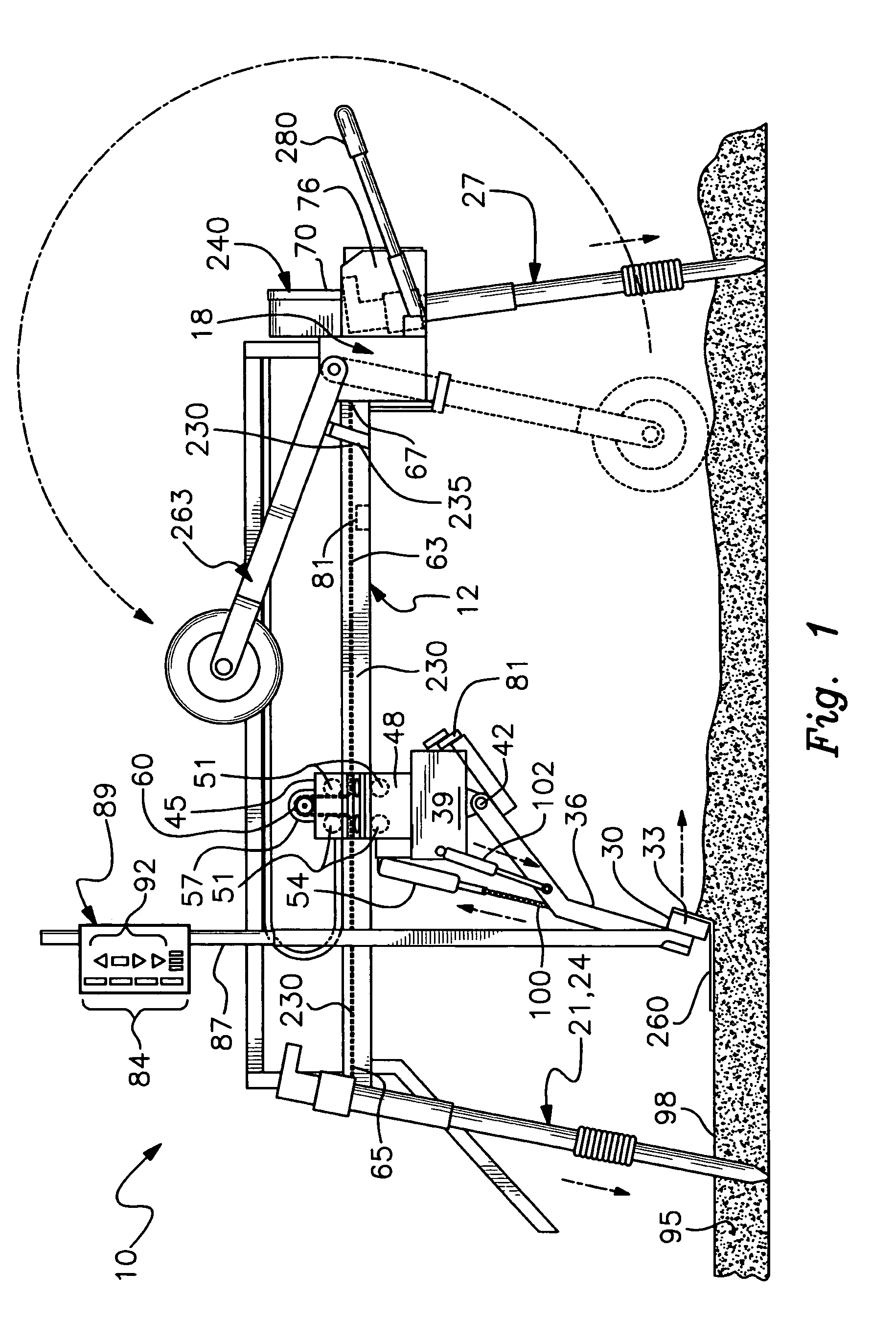
[0021]Detailed descriptions of the preferred embodiment are provided herein. It is to be understood, however, that the present invention may be embodied in various forms. Therefore, specific details disclosed herein are not to be interpreted as limiting, but rather as a basis for the claims and as a representative basis for teaching one skilled in the art to employ the present invention in virtually any appropriately detailed system, structure or manner.

[0022]Turning now to the drawings, as discussed above, embodiments of the present invention relate to a portable automatic screed. FIG. 1 is a side plan view of the portable automatic screed 10 in accordance with the present invention. As shown the portable automatic screed 10 has at least one fore and aft track formed of one or more fore and aft extending beams 12. The fore and aft extending beams 12 are connected to each other in a front thereby a cross bar 15, and in the rear thereof a rear cross bar beam or channel 18. The front ...


PUM


Abstract

A lightweight one man screed apparatus to automatically strike off and level uncured concrete flatwork, includes a tri-pod framework beneath which a cutting / leveling member operates. The apparatus is controlled by two grade setting devices, adjustably mounted to the screed tool, which may be adjusted relative to a laser plane generating system. Physical control of the screed member may be provided by at least one screed tool pivotal arm assembly moved for and aft by a carriage operated under the tri-pod framework within a fore and aft footprint. The screed tool is adjusted to grade by being raised or lowered by at least one linear actuators responding to an electronic controller. When moving the framework and screed assembly into freshly poured concrete, an operator is assisted by retractable wheels. The wheels are rotationally stowable or used deployed as part of the tripod / transport system facilitating mobility.

Description

CROSS REFERENCE TO RELATED APPLICATIONS[0001]This application claims priority of Provisional Patent Application Ser. No. 60-555,497, filed on Mar. 22, 2004.BACKGROUND OF THE INVENTION[0002]The present invention relates generally to a screeding device for uncured concrete floors and surfaces and more particularly to a lightweight self leveling automatic screed apparatus which may be easily transported, easily knocked down and reassembled, and used by one person or a small crew. The lightweight screeding device of the present invention is particularly suited for over ground sites as well as any site requiring portability of the screed apparatus such as elevated or basement floors, driveways, or slabs to be placed by small crews and / or minimally experienced personnel.BACKGROUND OF THE INVENTION[0003]Concrete screeds are used by personnel in the building industry to place and level uncured concrete to form a slab or floor. In its most simplistic form, a straightedge such as wooden 2″×4″...

Claims


Application Information

Patent Timeline
Patent Type & Authority Patents(United States)
IPC IPC(8): E01C19/00E01C19/22E01C19/38E04F21/24
CPCE04F21/24E04F21/244E04F21/242
Inventor JACKSON, GERALD MCLAIN
Owner JACKSON GERALD MCLAIN
Why Eureka
Try Eureka