In situ media defect image analysis

Inactive Publication Date: 2007-04-17
SEAGATE TECH LLC
View PDF19 Cites 20 Cited by
  • Summary
  • Abstract
  • Description
  • Claims
  • Application Information

AI Technical Summary

Benefits of technology

[0007]The present invention is a method or apparatus for analyzing a data storage device containing a transducer head positionable adjacent a data storage media surface. First, a defect is detected in a region of the surface. Two or more readback signals are obtained, each received during a respective pass of the transducer head adjacent the defective region. The signals are then combined to define a category fo

Problems solved by technology

First, a defect is detected

Method used


Image

  • In situ media defect image analysis
  • In situ media defect image analysis
  • In situ media defect image analysis

Examples


first embodiment

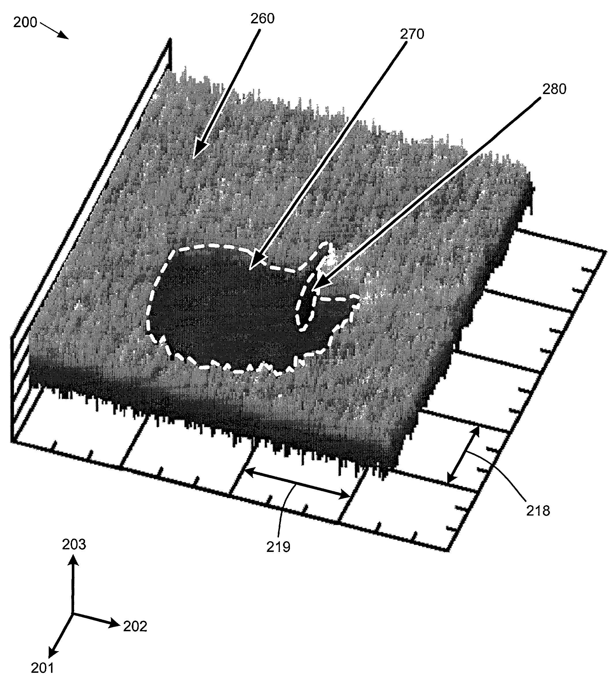
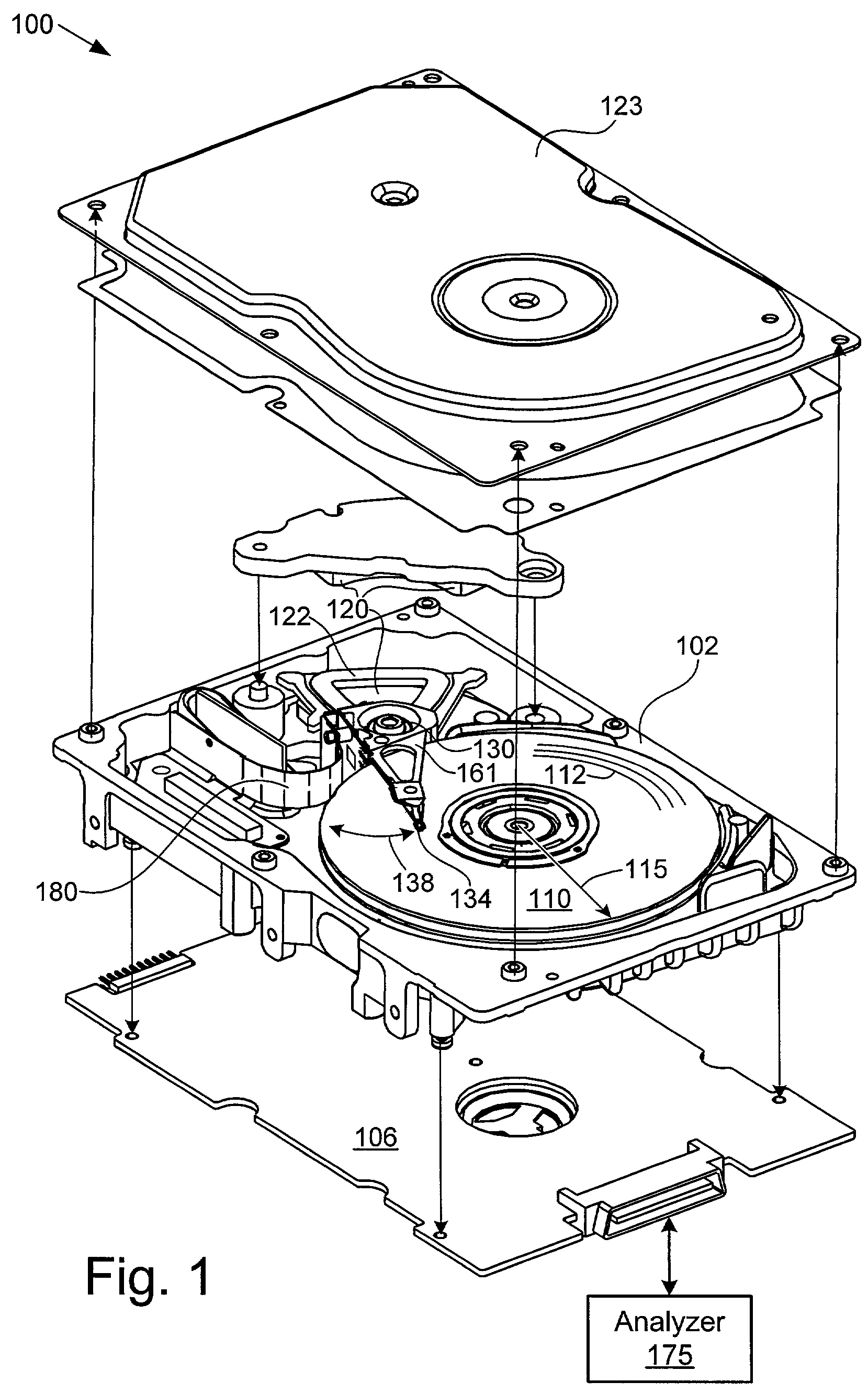
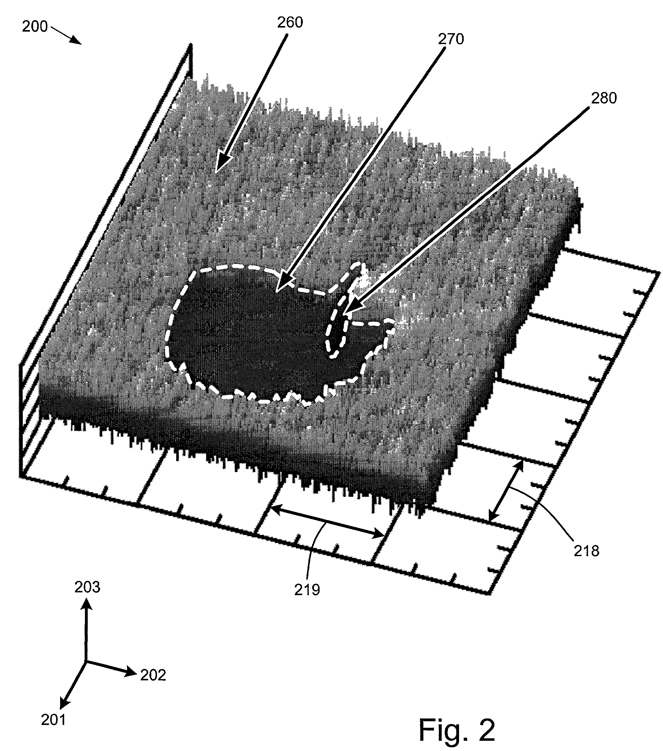
[0047]Alternatively characterized, the present invention is a method (such as 500,800) or apparatus (such as 106,175) for analyzing a data storage device (such as 100) containing a transducer head (such as 134) positionable adjacent a data storage media surface. First, a defect (such as 270, 358, 658) is detected in a region of the surface. At least two readback signals are obtained (such as by steps 523,541), each received during a respective pass of the transducer head adjacent the defective region. It is also desirable to obtain additional readback signals characterizing nearby regions (such as 260,603) with greater clarity. The signals are then combined to define a category for the defective region, either automatically (e.g. by circuitry on controller board 106 or analyzer 175, configured to implement method 800) or by visual examination (see FIG. 5). Preferably, all of the read signals are received from the transducer head while the data storage device remains sealed with a to...

second embodiment

[0048]In a second embodiment, a value is assigned (such as a length value assigned in step 846 of FIG. 8) to each of the defective regions belonging to a category. The data storage device is disqualified (such as by step 1077) if an aggregation of the assigned values exceeds a predetermined threshold (such as a distance of one thousand nominal track widths). Otherwise, the data storage device is usually qualified (i.e. marked as acceptable). The threshold is preferably determined according to an outcome of conventional failure analysis (such as by method 1050), which assesses the general level of risk that the cause of the defective region will cause subsequent loss of media performance. Advantageously, this method requires such analysis for at most a minority of the data storage devices having defects in that category.

third embodiment

[0049]In a third embodiment, a taxonomy having only a small number (at most 10 to 100) of primary categories is defined, each with a respective profile (such as by method 800). That is to say that the assigning step is completed while the combination of readback signals has been compared against a small number of profiles each corresponding to a respective category, the assigned category being one of the respective primary categories. In this way, the defective region is meaningfully described in a taxonomy having at most about 100 identifiers. (Note that a “primary” category is defined to exclude categories having profiles that are so narrow that no defects match the profile in a typical population of 50 devices.)

[0050]At least one of the categories is preferably associated with a scratch, and has a profile incorporating a minimum measure of length relative to width (such as by step 844). An least one of the other categories is preferably named as “unreliable” or “corrosion-indicat...


PUM


Abstract

The present invention is a method or apparatus configured for analyzing a data storage device containing a transducer head positionable adjacent a data storage media surface. First, a defect is detected in a region of the surface. Two or more readback signals are obtained, each received during a respective pass of the transducer head adjacent the defective region. The signals are then combined to define a category for the defective region, either automatically or by visual examination of an image. Preferably, all of the read signals are received from the transducer head while the data storage device remains sealed in a substantially opaque chamber. That way, the media defects of an entire population of data storage devices can be analyzed quickly, disassembling the drives for direct visual analysis only on a selective basis.

Description

RELATED APPLICATIONS[0001]This application claims priority of U.S. provisional application Ser. No. 60 / 296,025, filed 4 Jun. 2001.FIELD OF THE INVENTION[0002]This application relates generally to data storage devices and more particularly to an apparatus and method for analyzing media defects.BACKGROUND OF THE INVENTION[0003]Data information is stored in a magnetic medium by magnetizing a small area of the magnetic media. Small, random defects or flaws in the thin layer of magnetic material for a rigid disc can result in storage and subsequent playback of erroneous data bits. These erroneous data bits are created when data information is initially written into a defective area of the disc. These erroneous data bits are then subsequently read from the disc. A data bit error for a particular bit corresponding to a particular area of the disc is caused either by the magnetization for a bit being missing or by magnetization being added at the storage location. To locate defects in the t...

Claims


Application Information

Patent Timeline
IPC IPC(8): G11B5/02G11B5/012G11B20/18G11B27/36G11B33/10
CPCG11B5/012G11B20/1816G11B27/36G11B33/10G11B2220/20
Inventor KOSHKINA, OLGA VALERIEVNAARNAOUT, BADIH MOHAMADNAJI
Owner SEAGATE TECH LLC
Why Eureka
Try Eureka