Closure with tear strip

a technology of tear strips and closures, applied in the field of plastic containers/closure combinations, can solve the problems of preventing efficient stacking of closures for storage, affecting the effectiveness of gripping, and affecting the gripping effect of users, so as to facilitate the removal of tear strips, reduce material, and add to the effect of gripping

Inactive Publication Date: 2007-04-24
LETICA
View PDF27 Cites 90 Cited by
  • Summary
  • Abstract
  • Description
  • Claims
  • Application Information

AI Technical Summary

Benefits of technology

[0006]In the preferred embodiment of the tear strip aspect of the invention, the pull tab includes an inner gripping surface having ribs formed therein in such a way as to form a concavity which adds to the effectiveness of the grip. An outer surface of the pull tab includes one or more substantially linear ribs protruding in a substantially vertical arrangement therefrom. The combination of ribs and the recessed grip area provides a more secure grip for tearing the pull tab away from a frangible connection. Once the pull tab has been broken away, the ribs provide a gripping feature to facilitate the removal of the tear strip from the closure skirt. The recessed area further includes an opening formed in the skirt wall around the perimeter of the pull tab. The opening forms an arrow shaped element indicating the direction for pulling and removing the tear strip from the skirt.
[0007]Another aspect of the invention involves the design of a zig-zag rib structure into the interior of the closure to reduce material, add strength, and minimize warpage.

Problems solved by technology

Prior art tear strips can be difficult for a user to access and to grip as the tab is broken away and the tear strip is removed from the outer periphery of the closure.
However, this method prevents efficient stacking of closures for storage.
This approach uses additional plastic material, adds weight and can give rise to warpage problems in critical areas of the closure.

Method used


Image

  • Closure with tear strip
  • Closure with tear strip
  • Closure with tear strip

Examples


Embodiment Construction

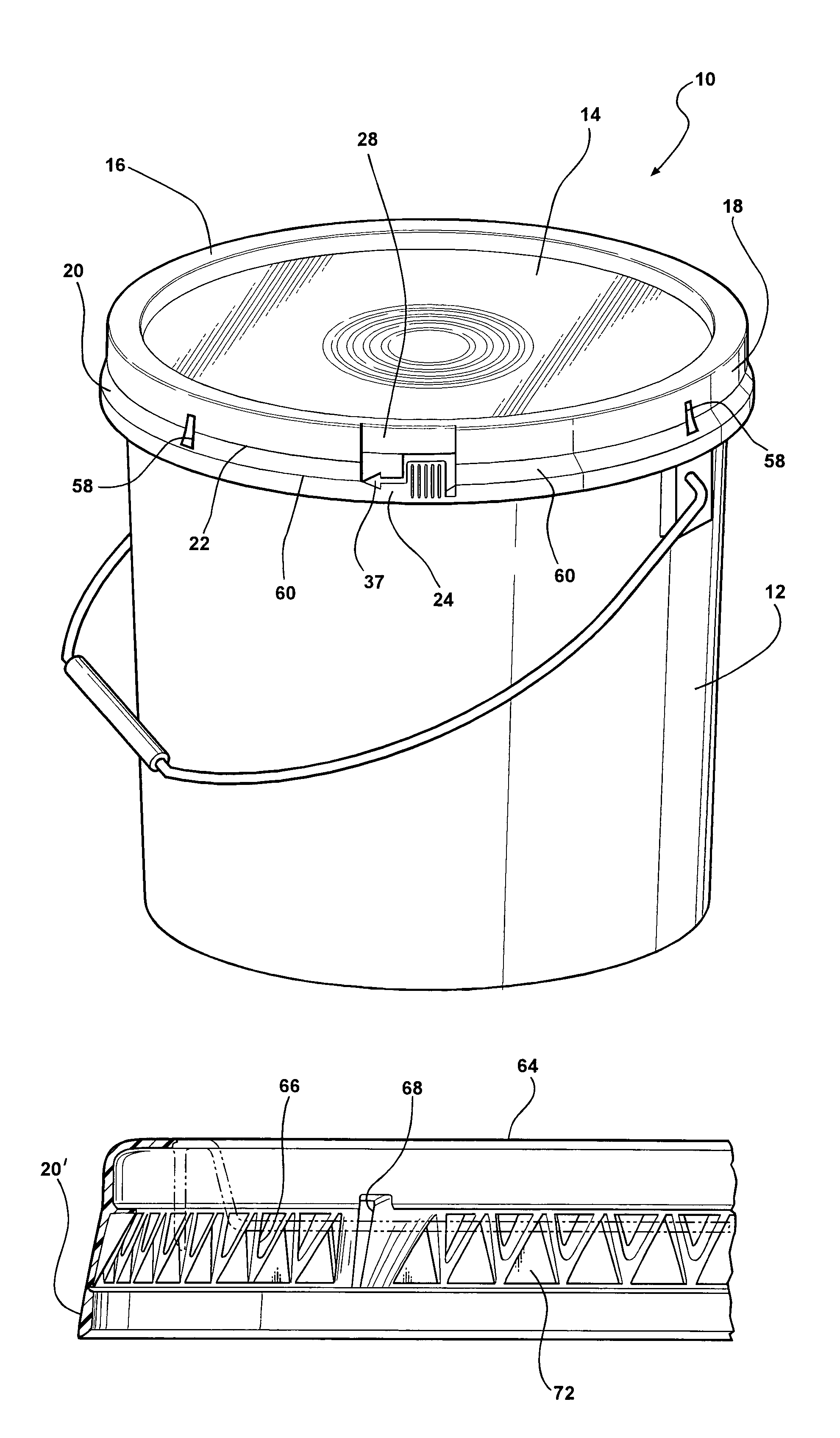
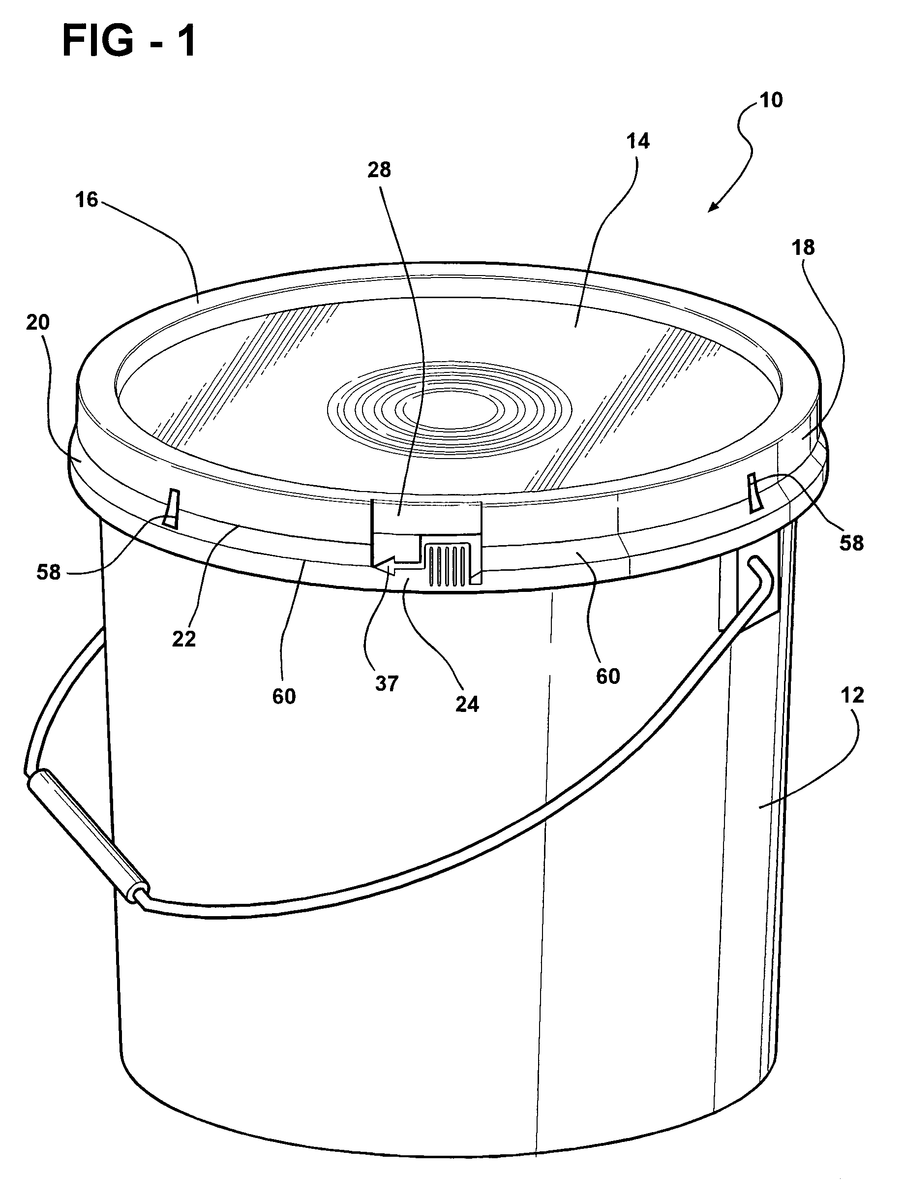
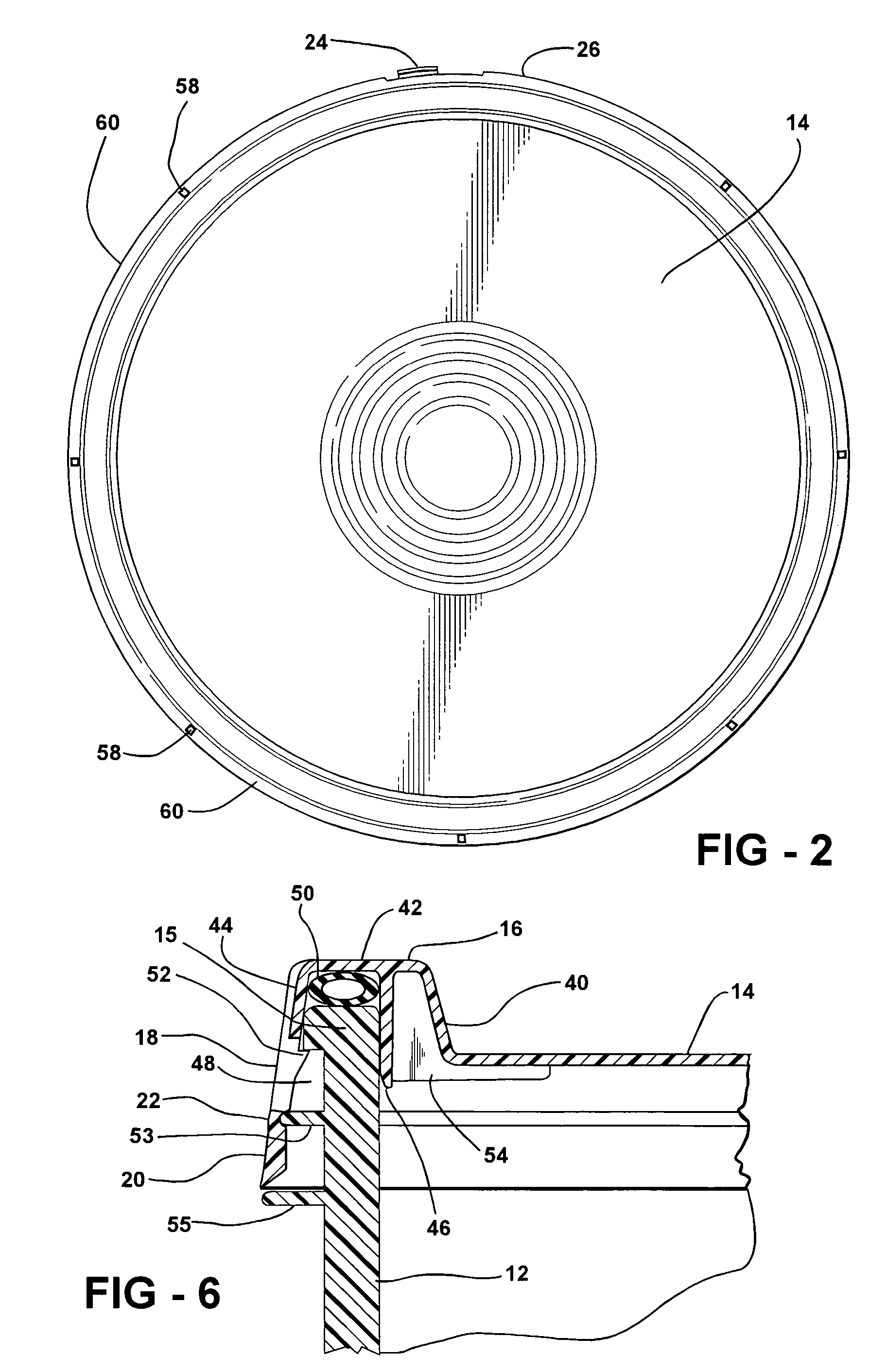
[0020]FIGS. 1–6 illustrate a first embodiment of the invention as the combination of an injection molded plastic closure 10 and an open top cylindrical container 12 of three to six gallon capacity. In such capacity, the closure is about 12 inches in outside diameter; these size and capacity numbers are given by way of example only. The material is preferably polyethylene but may also be polypropylene and / or other moldable polymers. The closure 10 includes a substantially planar deck portion 14 peripherally bounded by an inverted U-shaped channel 16, to receive the upper rim 15 of container 12, and a peripheral skirt 18 which overlies the upper wall of the container when installed. A tear strip 20 is formed integrally with the skirt 18 in the injection molding process. The tear strip 20 is removable from the skirt 18 via a tear line 22 of substantially reduced thickness and tensile strength relative to the rest of the skirt 18. A breakaway pull tab 24 is positioned substantially flus...


PUM

PropertyMeasurementUnit
diameteraaaaaaaaaa
strengthaaaaaaaaaa
hoop strengthaaaaaaaaaa

Abstract

A closure for covering an opening of a container. The closure includes an inverted U-shaped peripheral channel for receiving the rim of a container therein. A tear strip is formed with the skirt of the closure via a tear line that circumscribes the skirt. A breakaway pull tab having an inner surface with U-shaped ribs, the combination of the surface and ribs being such as to provide a concavity which assists in gripping the tab to pull the strip away. Linear vertical ribs may be provided on the outer surface to provide further assistance in the gripping function. The skirt includes a recessed area underlying the pull tab for providing access to the pull tab. An alternative embodiment uses a zig-zag structure of strengthening ribs in the skirt to reduce the amount of material necessary to provide the undercut. This reduces the probability of warpage in the closure structure.

Description

FIELD OF THE INVENTION[0001]This invention relates to plastic container / closure combinations and more particularly to an improved closure structure.BACKGROUND OF THE INVENTION[0002]Injection molded plastic containers and lock-on closures are in popular use for packaging a wide variety of products in quantities of one to six gallons. Examples include asphalt sealant, paint, drywall putty and food products. The “lock-on” feature is typically provided by an undercut in the closure which snaps around a peripheral edge flange in the open top of the container. The hoop strength of the closure is such that means must be designed into the closure to facilitate its removal. The two most common such means include (1) tear strips which are removed to reduce the force of the locking mechanism and (2) windows or apertures in the closure skirt which permit the skirt to be fractured at several circumferentially spaced locations. These mechanisms can also be used in combination.[0003]Prior art tear...

Claims


Application Information

Patent Timeline
Patent Type & Authority Patents(United States)
IPC IPC(8): B65D17/40B65D41/16B65D43/02B65D43/06B65D55/06
CPCB65D43/0237B65D2543/00092B65D2543/00296B65D2543/00518B65D2543/00555B65D2543/00629B65D2543/00685B65D2543/0074B65D2543/00796B65D2543/00972
Inventor SCHWARZ, STEFAN H.
Owner LETICA
Why Eureka
Try Eureka