Illuminated device

a technology of illumination device and light source, which is applied in the direction of luminescence, lighting and heating apparatus with built-in power, etc., can solve the problems of difficult to see key holders, switch plates, number plates, etc., and achieve the effect of simple and easy manufacturing

Inactive Publication Date: 2007-04-24
REILLY KEVIN
View PDF5 Cites 5 Cited by
  • Summary
  • Abstract
  • Description
  • Claims
  • Application Information

AI Technical Summary

Benefits of technology

[0021]Another object of the present invention is to provide an illuminated article which is relatively simple and easy to manufacture.

Problems solved by technology

For example, key holders, switch plates, number plates, and the like are difficult to see in darkened spaces and during the nighttime.
Although satisfactory in providing visibility to such articles, these methods are expensive or cumbersome.

Method used


Image

  • Illuminated device
  • Illuminated device
  • Illuminated device

Examples


Embodiment Construction

[0041]Various aspects of the present invention will evolve from the following detailed description of the preferred embodiments thereof which should be taken in combination with the heretofore-delineated drawings.

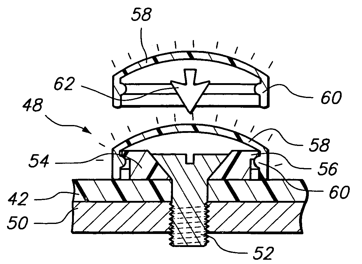
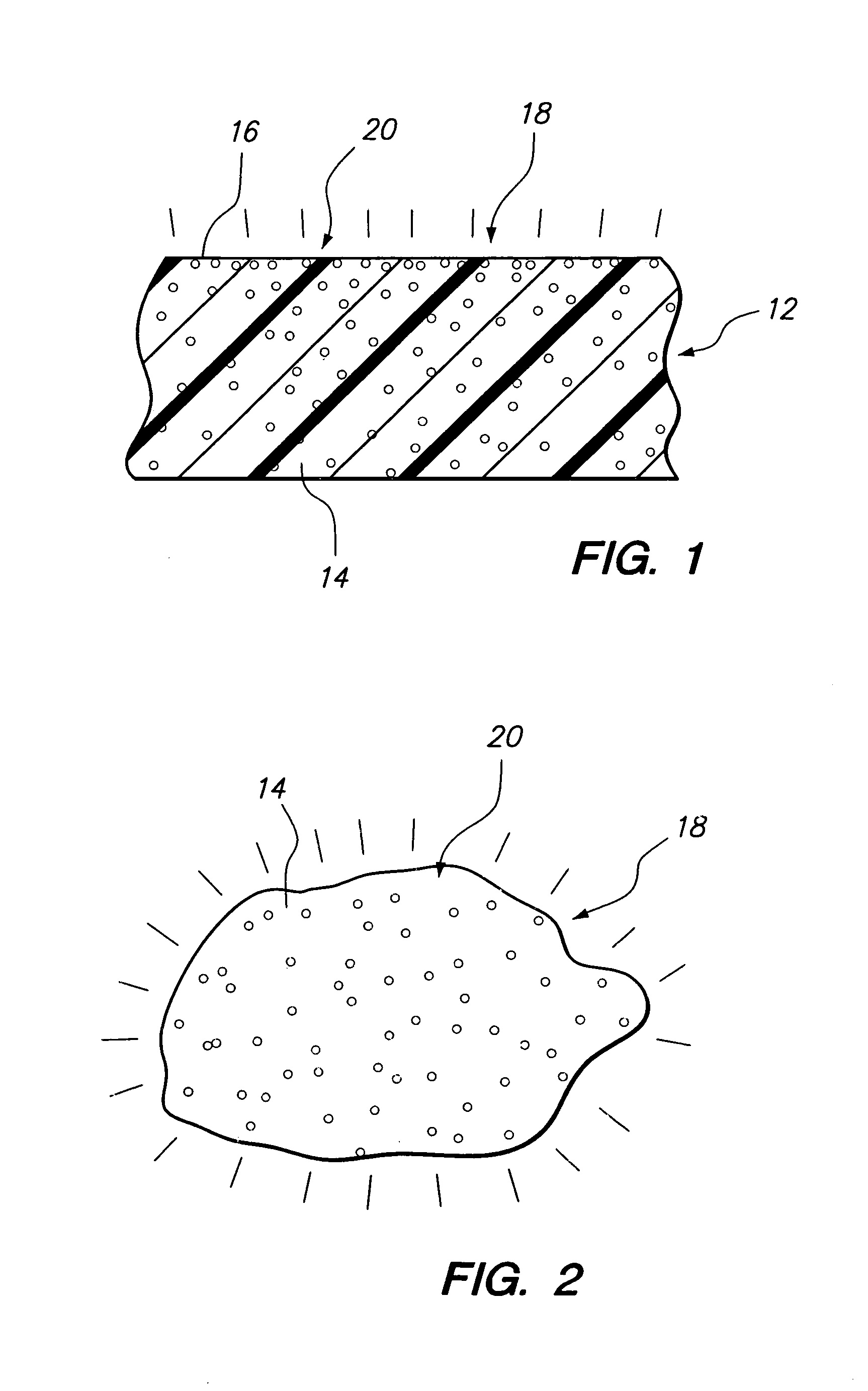
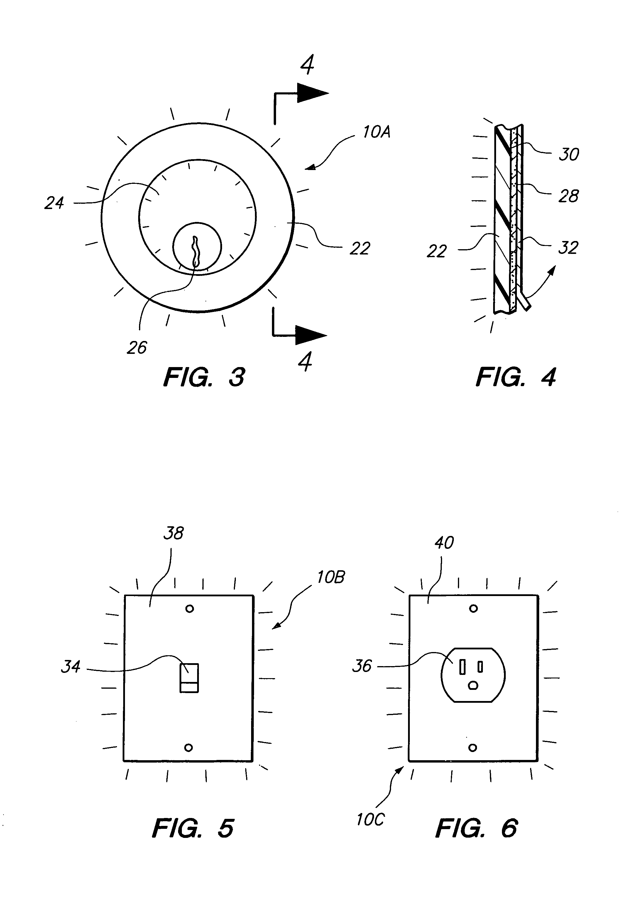
[0042]The invention as a whole is shown in the drawings by reference character 10 followed by an upper case letter to denote various embodiments of the same. Article 10 includes as one of its elements a base member 12. Base member 12 is generally formed of a polymeric of plastic material such as polypropylene, polyethylene, ethylene vinyl acetate, polyvinyl chloride, and the like. Such polymeric materials are easily molded for formation into articles of various configurations by an injection molding process. As shown in FIGS. 3–6, articles 10A, 10B, and 10C are depicted in the form of a lock collar, switch plate, and an outlet plate a key sleeve identifier, respectively. Other similar articles may be embedded in base member 12. Base member 12, depicted in FIGS. 1 and 2 micr...


PUM


Abstract

An illuminated article utilizing a base member having an outer surface. A plurality of luminescent bodies are embedded in the base member for exposure of the same at the outer surface of the base member. The article may be formed into various shapes to illuminate operable members such as light switches, electrical plugs, keyholes, and the like.

Description

CROSS-REFERENCE TO RELATED APPLICATIONS[0001]The present application is a Continuation-in-Part of U.S. patent application Ser. No. 10 / 635,513; filed 7 Aug. 2003 now abandoned.BACKGROUND OF THE INVENTION[0002]The present invention relates to a novel and useful illumination system.[0003]It is often necessary to illuminate controls and other articles which access spaces. For example, key holders, switch plates, number plates, and the like are difficult to see in darkened spaces and during the nighttime.[0004]In the past, persons accessing such articles have been forced to carry flashlights or install permanent lighting in or about the articles to be operated in the dark. Although satisfactory in providing visibility to such articles, these methods are expensive or cumbersome.[0005]The other systems have been proposed such as those shown in U.S. Pat. Nos. 1,385,300, 1,522,169, 2,032,540, and 2,515,820 which utilize luminous coatings or paints to illuminate switches.[0006]U.S. Pat. Nos. ...

Claims


Application Information

Patent Timeline
Patent Type & Authority Patents(United States)
IPC IPC(8): F21V33/00
CPCF21S9/02F21V23/0442
Inventor REILLY, KEVIN
Owner REILLY KEVIN
Why Eureka
Try Eureka