Hybrid transmission

Inactive Publication Date: 2007-04-24
NISSAN MOTOR CO LTD +1
View PDF14 Cites 22 Cited by
  • Summary
  • Abstract
  • Description
  • Claims
  • Application Information

AI Technical Summary

Benefits of technology

[0007]It is, hence, an object of the present invention to provide a hybrid transmission in which the motor/generator(s) are not directly coupled to road wheels even in the low-side transmission gear ratio (shift ratio) region including the reverse gear ratio and the

Problems solved by technology

However, since, in the above-described alternative type hybrid transmission, the clutch and the brake, both for the gear (or shift) mode switching purpose, are switched between operations and non-operations on an output axle portion of the transmission, a large torque needs to be received at these clutches and brakes.
This involve

Method used


Image

  • Hybrid transmission
  • Hybrid transmission
  • Hybrid transmission

Examples


first embodiment

[0041](First Embodiment)

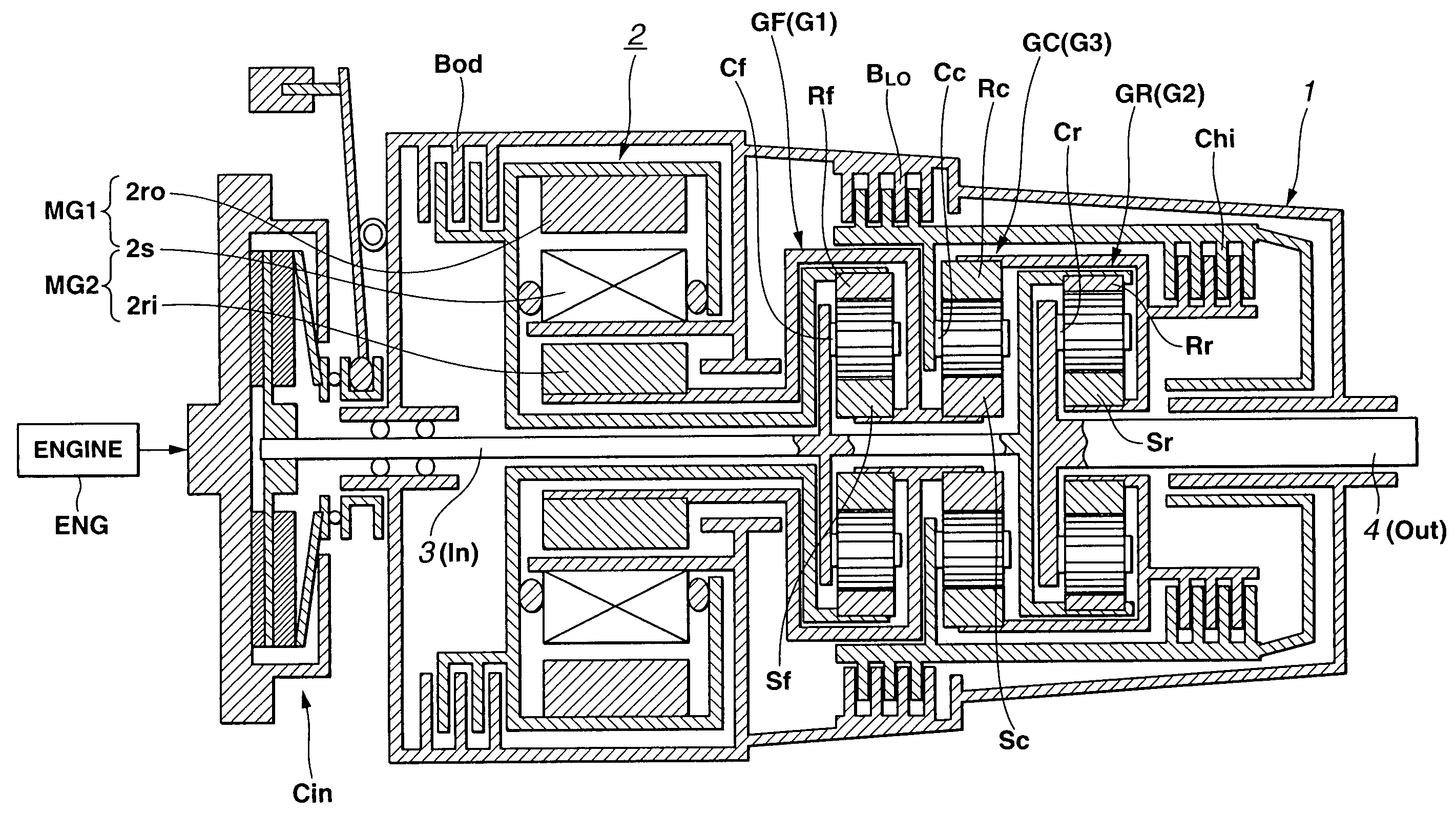
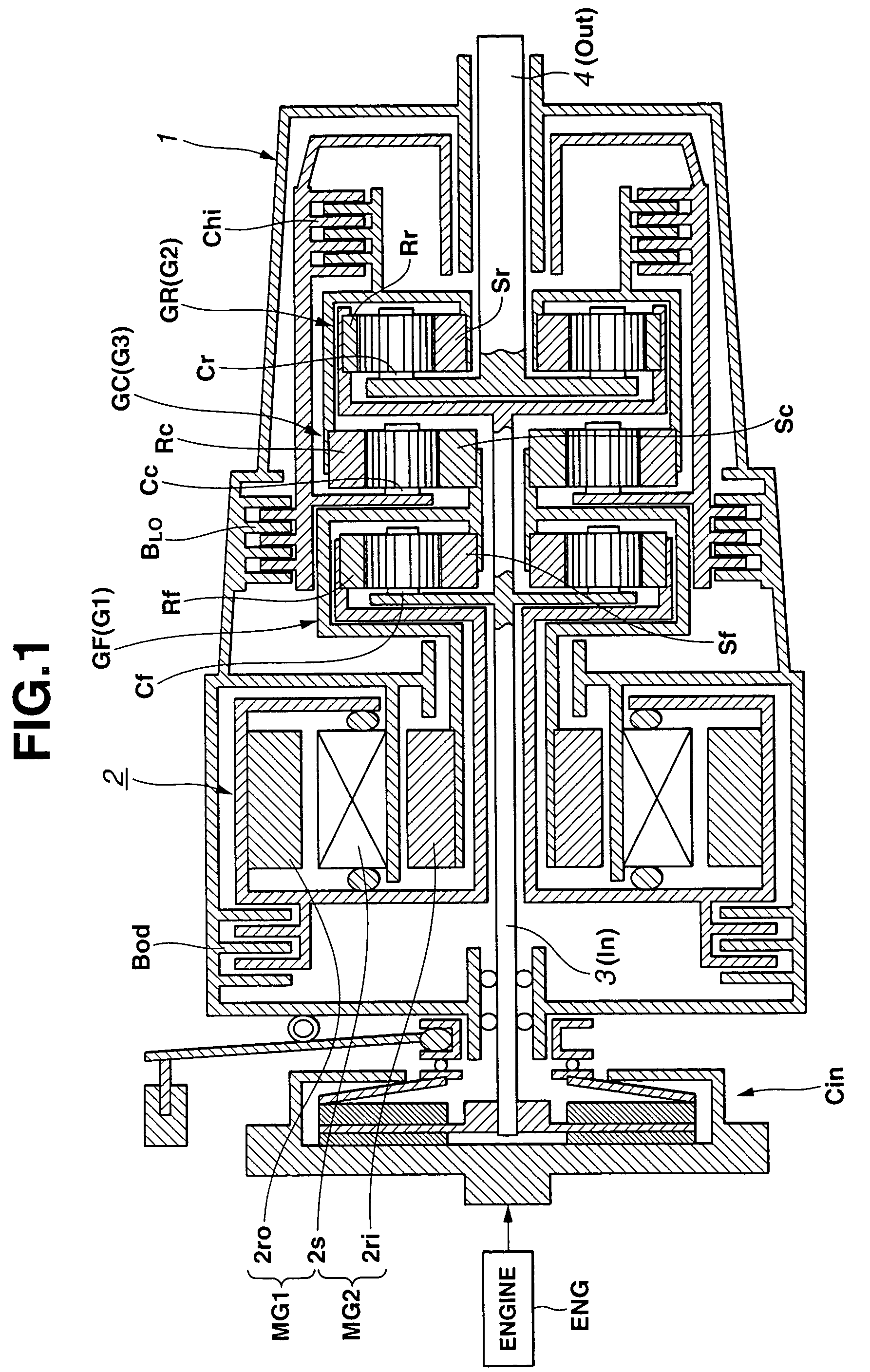
[0042]FIG. 1 shows a hybrid transmission in a first preferred embodiment according to the present invention. In this embodiment, the hybrid transmission is suitable for a transmission of a front-engine-and-rear-drive (FR) vehicle.

[0043]In FIG. 1, reference numeral 1 denotes a transmission casing. In transmission casing 1, three simple planetary gear sets at a right end (rear end most far way from an engine ENG and in an axial direction (horizontal direction as viewed through FIG. 1) thereof are aligned coaxially. That is to say, three simple planetary gear sets are a front side planetary gear set GF located at a position nearest to engine ENG, a center planetary gear set GC, and a rear side planetary gear set GR. In addition, in transmission casing 1, a motor / generator couple which is constituted by, for example, a compound-current double-layer motor 2 is coaxially disposed with respect to three planetary gear sets at a leftmost side of casing 1 (front side n...

second embodiment

[0062](Second Embodiment)

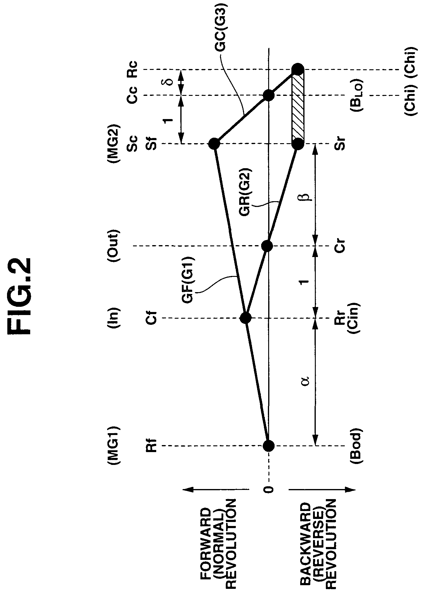
[0063]FIG. 3 shows a hybrid transmission in a second preferred embodiment according to the present invention. FIG. 4 shows a lever diagram of the hybrid transmission in the second embodiment shown in FIG. 3. In the same way as described in the first embodiment, front side planetary gear set GF constitutes first differential unit G1 according to the present invention, center planetary gear set GC constitutes third differential unit G3, and rear side planetary gear set GR constitutes the second differential unit G2 according to the present invention. In the second embodiment, carrier Cf and sun gear Sr are coupled to input axle 3 to which the revolution of engine ENG is inputted (as denoted by input portion In within the lever diagram in FIG. 4) and output axle 4 (as denoted by output portion Out in the lever diagram of FIG. 4) is coupled to carrier Cr.

[0064]In other words, in the low-side gear ratio region including the reverse gear ratio than the gear shift ...

third embodiment

[0065](Third Embodiment)

[0066]FIG. 5 shows a hybrid transmission in a third preferred embodiment according to the present invention. FIG. 6 shows the lever diagram of the hybrid transmission shown in FIG. 5. As described in each of the first and second embodiments, front side planetary gear set GF constitutes a first differential unit G1 according to the present invention, rear side planetary gear set GR constitutes second differential unit G2, and center planetary gear set GC constitutes third differential unit G3.

[0067]In the same way as described in the cases of FIGS. 1 and 2, sun gears Sf and Sc are mutually coupled and integrated in the same way as the cases of FIGS. 1 and 2. The mutually coupled element is coupled to second motor / generator MG2 (inner rotor 2ri). First motor / generator MG1 (outer rotor 2ro) is coupled to ring gear Rf. Ring gears Rc and Rr are mutually coupled and this ring gear coupled element is enabled to be coupled to carrier Cc by means of high-clutch Chi. T...


PUM


Abstract

In a hybrid transmission, input and output side motor/generators (MG1, MG2) and input and output portions (In, Out) are coupled to two sets of the differential units (G1, G2) in such a manner that, under a selection of a first predetermined gear ratio, in a revolution speed order, the input side motor/generator (MG1), the input portion (In) from a prime mover (engine), the output portion (Out) toward a vehicular drive system, and the output side motor/generator (MG2) are coupled to the respective revolvable elements of the two sets of the differential units (G1, G2) and the output side motor/generator is coupled to any one of the revolvable elements of the two sets of the differential units including those revolvable elements thereof which do not contribute to a revolution of the output portion.

Description

BACKGROUND OF THE INVENTION[0001]1. Field of the Invention[0002]The present invention relates generally to a hybrid transmission suitable for a hybrid vehicle in which a prime mover such as an engine and at least one motor / generator (a motor functions as a generator or vice versa) are mounted. The present invention relates particularly to a gear shift control apparatus for the hybrid transmission which is capable of making a differential unit which couples between the prime mover (engine) and motor / generator(s) carry out a continuously variably transmitting operation using at least two differential units coupling between the prime mover and the motor / generator.[0003]2. Description of the Related Art[0004]A hybrid transmission is generally of a series-connection type, a parallel-connection type, and a combination type of series-and-parallel-connection. In any type of the hybrid transmissions, a whole or part of engine revolution energy is, once, converted into an electrical energy by...

Claims


Application Information

Patent Timeline
IPC IPC(8): F16H3/72B60K1/02B60K6/26B60K6/365B60K6/445B60K17/04B60L50/16B60W10/02F16H3/64F16H3/66
CPCB60K6/365B60K6/405B60K6/445B60K6/543B60W10/02F16H3/728B60K1/02B60W20/00B60W2520/06F16H2037/102F16H2037/104F16H2200/201F16H2200/2035Y02T10/6239Y02T10/62B60W30/18027B60K17/04B60W10/08B60W2510/10
Inventor OSHIDARI, TOSHIKAZUKARGAR, KEYVANPOUPON, JOELGOTOH, YUUJIYAMAUCHI, YASUHIROYATABE, KAZUO
Owner NISSAN MOTOR CO LTD
Why Eureka
Try Eureka