Connection rod for screw or hook polyaxial system and method of use

a polyaxial system and connection rod technology, applied in the field of adjustable rods, can solve the problems of inability to predict the exact final position of the bone screw, the use of fixed screws, and the uncertainty of exact bone formation and shape within an individual patient, and achieves the effects of low profile, easy installation, and large incision

Inactive Publication Date: 2007-04-24
RITLAND STEPHEN
View PDF339 Cites 317 Cited by
  • Summary
  • Abstract
  • Description
  • Claims
  • Application Information

AI Technical Summary

Benefits of technology

[0016]The attachment device may include additional features to enable the insertion of the head end of the tension link into the hollow core. The enlarged area of the attachment device may include an entry channel leading to the hollow core that accommodates the tension link head end so that the tension link may be advanced, shaft end first, until the head of the tension link is positioned within the hollow core. Additionally, the entry channel and the central aperture may be connected by a slot through the wall of the enlarged area. In this way, the tension link head end may be positioned within the hollow core without extending the entire length of the tension link beyond the enlarged area of the attachment device opposite the central aperture. The surgeon may place only the head end of the tension link at the entry channel, slide the tension link shaft through the tension link slot, and draw the head end into the hollow core. Alternatively, in lieu of an entry channel or tension link slot, the enlarged area may include one or more expansion slots. In this embodiment, the head of the tension link may be inserted into the hollow core through the central aperture by the application of enough force to expand the central aperture. Once the head of the tension link is properly received into the hollow core, the enlarged area returns to its original size and shape. Unwanted expansion of the enlarged area is prevented by the connector once the enlarged area is properly seated into a head receptacle on the connector during implantation. This maintains the head of the tension link within the hollow core.
[0019]The tension link may be provided with a projection to prevent undesirable rotation of the link when tightening or loosening the link nut, yet still enable angular displacement necessary to provide a polyaxial connection. In one embodiment, a link retainer, or a projection, may be provided on the shaft of the tension link. In this embodiment, it is necessary to provide a link retainer recess within the tension link cavity of the connector. In an alternative embodiment, the link retainer, or projection, may be provided at the intersection of the tension link shaft and the head end, and extending over a portion of the surface of the head end. In this embodiment, used with the attachment device embodiment including a tension link slot, the rotation may be prevented by contacting the link retainer with one side of the tension link slot. In either of the two foregoing embodiments, it is desirable to undersize the link retainer, relative to the link retainer recess or the tension link slot, so that the polyaxial freedom of the tension link and attachment device combination is not unduly limited. In an alternative embodiment, a retaining process, or small projection, may be provided on the tension link head. The retaining process should be positioned such that the retaining process is within the entry channel. Undesired rotation may be prevented by contacting the small projection with the wall of the entry channel.
[0022]In either of the two foregoing connector embodiments, it may be desirable to secure the rod within the rod aperture without clamping to the extent axial movement of the rod within the rod aperture is prevented. In this way, for example, the spine may settle under its own weight and provide a better healing environment for the bone. In conjunction with this embodiment, the implant component may be supplied with flanges, or other extensions to constrain axial movement of the implant component within a desired range.
[0024]Based on the foregoing summary, a number of worthwhile aspects of the present invention can be readily identified. An attachment device is provided with a small and simple polyaxial adjustment mechanism. The minimal size of the enlarged area of the attachment device allows attachment of the device to human bone without significant displacement of human tissue. Therefore, the complexity of surgery and the following pain and discomfort of the patient may be minimized. The polyaxial nature of the device, combined with the small size, may allow a surgeon to attach the securement device to a secure portion of the human body without the need to remove bony processes to accommodate a larger attachment device. Additionally, a simple surgical implant assembly, including the polyaxial attachment device, is provided. The simplicity of the elements, and the assembly process thereof, may reduce the patient's time in surgery, thus reducing the risk and probability of surgical complications. Finally, a number of embodiments of the present invention may be used in combination to allow the surgeon great latitude in selection of materials. The surgeon may select from different embodiments of the attachment device, the tension link, and the connector to best fit the surgical implant parameters. With these choices the surgeon may then best determine which embodiments of which elements to select to minimize removal or displacement of bodily tissue or bone, and thereby reduce both the patient's risk of surgical complications and post-surgical pain and discomfort.
[0030]A method of use is also presented for the clamp device, wherein in a preferred embodiment the two attachment devices are installed by advancing an attachment device into each of two bone segments. The hollow core of each attachment device is then fitted with a the head of a tension link. Alternately, the tension link may be inserted into the hollow core of the tension link prior to insertion of the attachment devices into bone. After the attachment devices with their respective tension links are in place, one of the attachment devices is fitted with an interior rod member that includes a rod portion and an end connector in the form of a receptacle shaped like a socket. The socket includes a tension link cavity such that the shaft of the tension link is passed through the tension link cavity as the socket is being placed over the enlarged area of the first attachment device. A clamp comprising a lower and upper clamp portion is then assembled to grasp the rod portion of the interior rod member as the upper and lower clamp are connected to the second attachment device by passing the shaft of the second tension link through tension link cavities in the securing ends of the lower and upper clamp portions. Link nuts are then threaded on to exposed ends of the tension link shafts and are tightened. The position of the interior rod member can be adjusted within the clamp as the link nuts are tightened, thereby allowing the surgeon to adjust the size of the assembly to accommodate the patient's needs for a customized fit. The assembly minimizes the need to create a large incision because implantation work can be substantially performed from a direction perpendicular to the bone segments. Furthermore, this low profile assembly is relatively simple to install, thereby reducing surgery time over existing stabilizing devices.

Problems solved by technology

However, there are several problems with the use of fixed screws for anchoring spinal implants.
The exact final position of a bone screw is difficult, if not impossible, to predict prior to the exposure of the patient's bone.
This unpredictability results from the uncertainty of exact bone formation and shape within an individual patient.
Additionally, it can be difficult to predetermine the structure of the bone, i.e. whether the bone is soft or even osteoporotic.
Even if the final position of the screw can be predetermined, the necessary shape and position of a spinal rod implant may create unwanted stress upon the bone screw or the bone itself.
The alignment of the rod with several screws along the vertebrae compounds this problem and makes undesired stress much more probable.
Moreover, this misalignment may influence the extent and speed of correction of the spinal defect.
Unfortunately, the advantage of many of these designs comes at the expense of bulk in the connection means or complexity of implantation.
Such devices included complicated retention collets or securing systems that eliminate the device from functioning as a polyaxial system.
Moreover, this bulk may result in long-term muscular displacement that may lead to a patient's pain or discomfort.
Increased complexity of the installation procedure is undesirable because it increases a patient's time in surgery.
Increased operating time is known to increase the risk of many complications associated with surgery.
The additional time necessary to remove, or even temporarily dislocate, bone or muscular tissue also increases operating time, and thus the risk of complications.
In addition, the prior art fails to provide a low-profile multi-piece connector that includes poly-axial adjustability and that can be used to accommodate a variety of geometry requirements that may arise for certain patients.
The prior art also fails to provide a tool for implantation of an attachment device that has an entry channel for a tension link, or that otherwise has an expansion slot.
In addition to the above noted shortcomings of the prior art, the prior art also fails to provide a low-profile device that includes a connector that can be positioned at the very end of a stabilizing rod, thereby providing a device that does not disturb the adjacent vertebra.
The prior art also fails to provide a low-profile device that allows the rod length to be easily adjusted during implantation with a minimal amount of effort by the installing surgeon.
The prior art also fails to provide a rod implant that can be telescopically adjusted at the time of implantation.
In a rigid spinal implant system, the patient's spinal column may be unnaturally held apart by the structure of the implant.
It is possible that this stretching of the vertebrae, in relation to one another, results in delayed or incomplete healing of the bone.

Method used


Image

  • Connection rod for screw or hook polyaxial system and method of use
  • Connection rod for screw or hook polyaxial system and method of use
  • Connection rod for screw or hook polyaxial system and method of use

Examples


Embodiment Construction

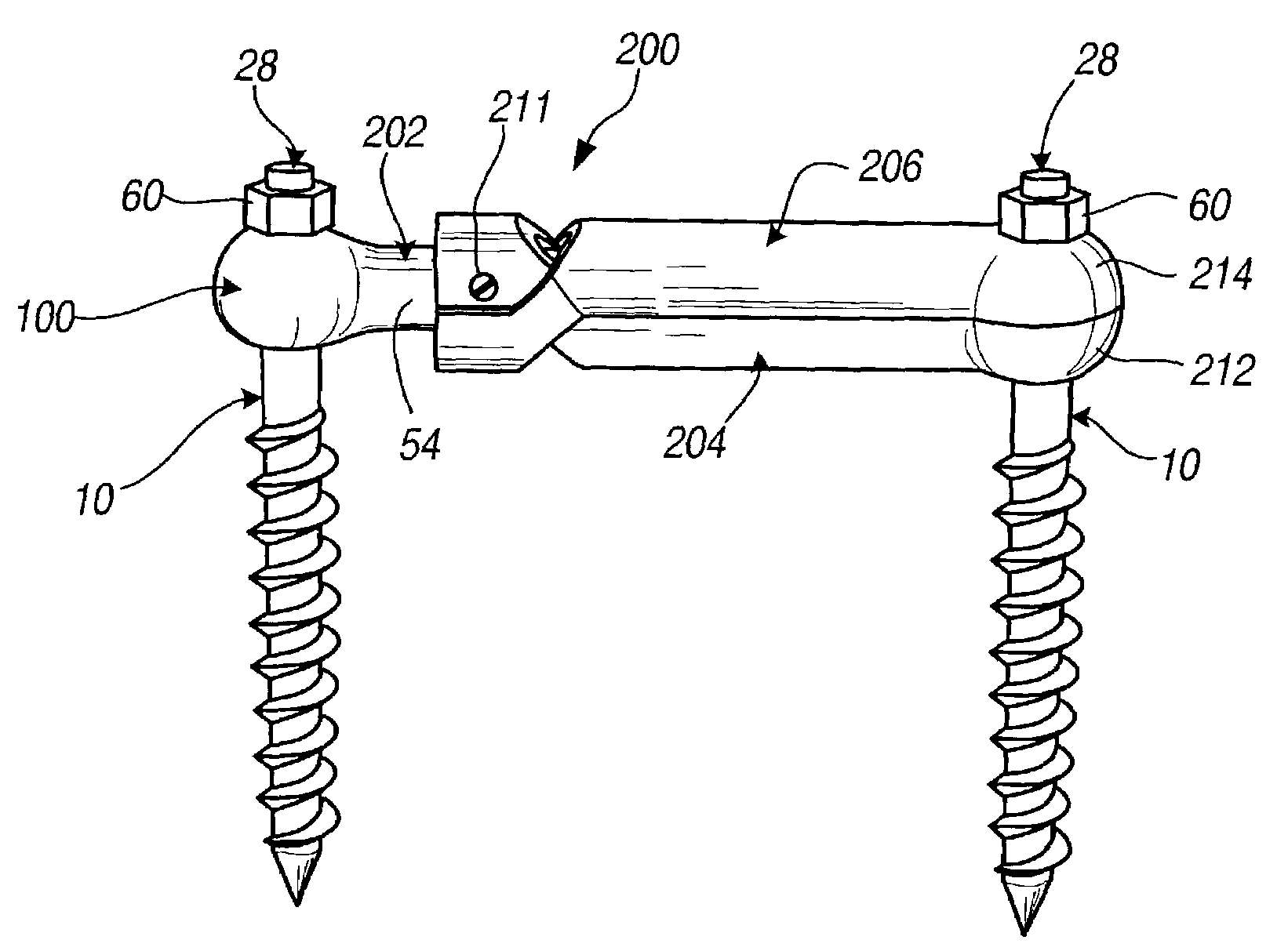
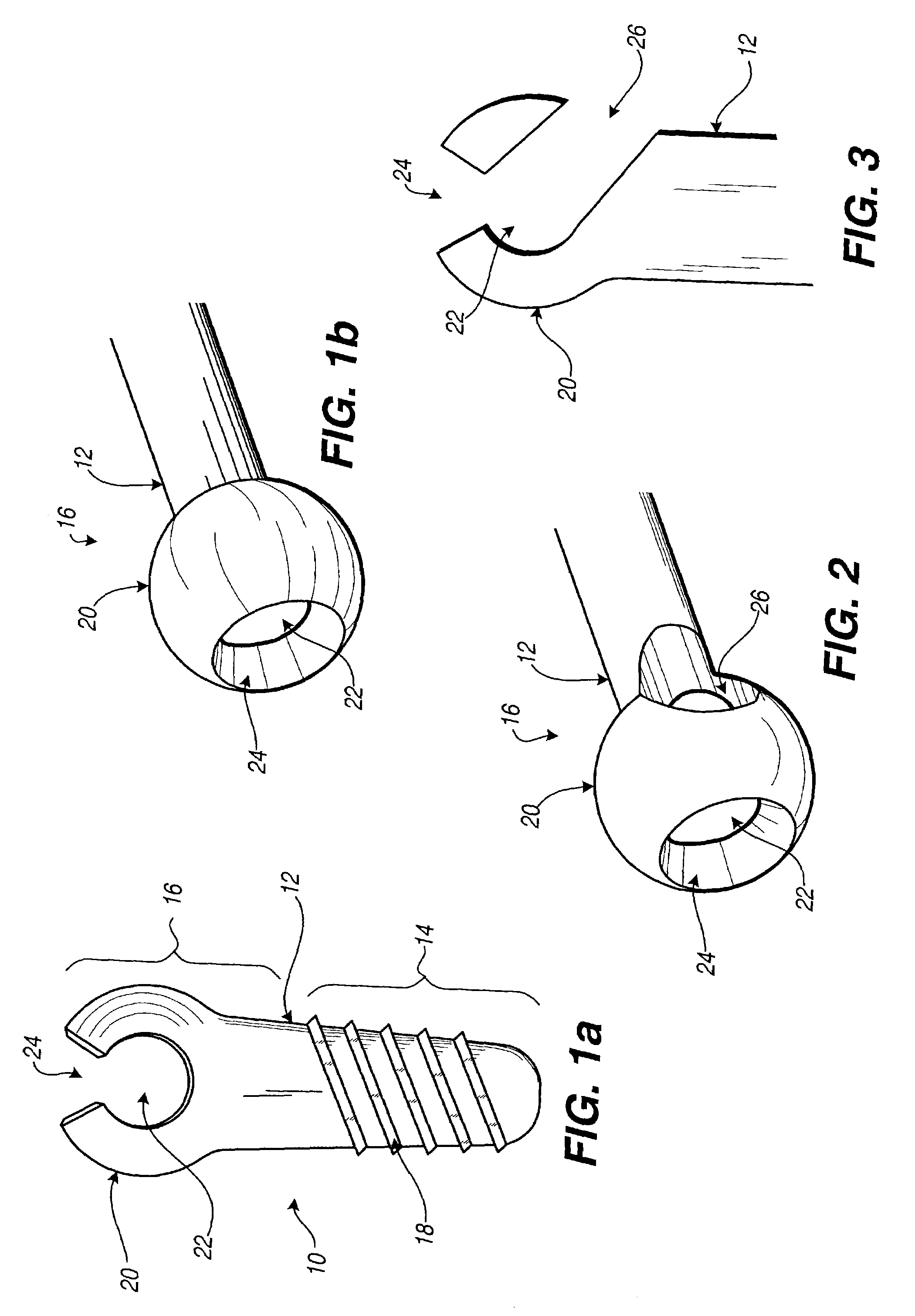
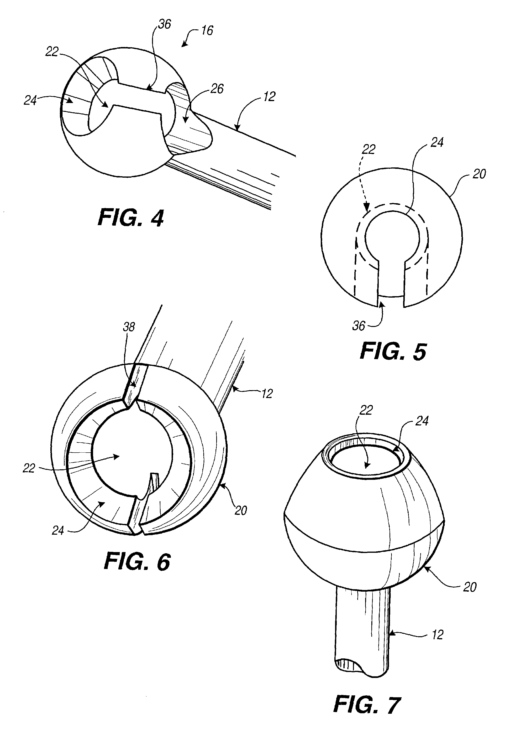
[0088]With reference to FIG. 1, one embodiment of the attachment device (or connection device) of the present invention is shown in partial cross-section. The attachment device 10 includes a shank 12 having a first end 14 and a second end 16. The first end 14 of the shank 12 includes a securement mechanism 18. As shown in FIG. 1, the securement mechanism 18 may be screw threads. It is noted, however, that the securement mechanism 18 may include any known method of securing one item to another. For example, the securement mechanism 18 may be a hook, a plate, a flange, or adhesive. In the case of the securement mechanism 18 as a flange or plate, the securement mechanism 18 may require additional hardware such as screws, bolts, or adhesive to secure the plate or flange to the intended object. In the case of the securement mechanism 18 as an adhesive, or requiring the additional use of adhesive, the adhesive would necessarily be applied to the securement mechanism 18, not included withi...


PUM


Abstract

A low-profile surgical implant assembly is provided that includes a connector device that is an integral part of a rod, the connector device allowing the rod to be attached directly to a bone screw, such as a pedicle screw. Another aspect of the invention is a clamp device that allows the length of a rod spanning to attachment devices to be adjusted at the time of implantation, and further allows the clamp device to be secured by tightening a securing end of the clamp at the attachment device. The assemblies are useful for insertion into bone and connecting a foreign object to bone via a polyaxial coupling mechanism. A method for implanting the assembly is also provided.

Description

CROSS-REFERENCE TO RELATED APPLICATIONS[0001]Priority is claimed from U.S. Provisional Patent Application No. 60 / 325,809 filed Sep. 28, 2001 entitled “Connection Rod For Screw or Hook Polyaxial System And Method of Use,” which is incorporated by reference in its entirety.FIELD OF THE INVENTION[0002]This invention relates generally to an adjustable rod for stabilizing a portion of the spine, or two or more bone segments and a method of using the same. More specifically, the device and method include a series of components that provide a low-profile configuration when assembled, thereby minimizing tissue displacement and interference with nearby joint articulation.BACKGROUND OF THE INVENTION[0003]The use of fixation devices for the treatment of vertebrae deformities and injuries is well known in the art. Various fixation devices are used in medical treatment to correct curvatures and deformities, treat trauma and remedy various abnormal spinal conditions. Treatment of these conditions...

Claims


Application Information

Patent Timeline
Patent Type & Authority Patents(United States)
IPC IPC(8): A61B17/56A61B17/70A61B17/58A61B17/88A61F2/44A61F2/46
CPCA61B17/7007A61B17/7014A61B17/7025A61B17/7037A61B17/7041A61B17/862A61B17/8883A61B17/7004A61B17/7049
Inventor RITLAND, STEPHEN
Owner RITLAND STEPHEN
Why Eureka
Try Eureka