Apparatus and method for thermally isolating a heat chamber

a technology of thermal isolation and apparatus, which is applied in the direction of lighting and heating apparatus, charge manipulation, furniture, etc., can solve the problems of reducing the heat transfer rate, reducing the thermal conductivity coefficient, and individual defective devices cannot be removed, so as to reduce the amount of heat, and reduce the effect of thermal conductivity

Inactive Publication Date: 2007-04-24
APPLIED MATERIALS INC
View PDF41 Cites 1 Cited by
  • Summary
  • Abstract
  • Description
  • Claims
  • Application Information

AI Technical Summary

Benefits of technology

[0019]The present invention provides an improved apparatus for connecting a heat chamber or another high temperature process chamber to a second chamber, such as a central transfer chamber, in a closed environment suitable for modular architecture based substrate processing in such a manner that heat transfer from the heat chamber or another high temperature process chamber to the second chamber is minimized. The apparatus of the present invention includes a thermally isolating interface, which has a reduced thermal conductivity coefficient, that abuts the second chamber. This thermally isolating interface reduces the amount of heat that is transferred from the heat chamber or other high temperature process chamber to the second chamber. Furthermore, in some embodiments of the present invention, the thermally isolating interface includes one or more recesses so that the surface area between the thermally isolating interface and the second chamber is minimized. Reduction in this surface area, in turn, minimizes thermal transfer between the heat chamber or other high temperature process chamber and the second chamber. Thus, the apparatus of the present invention prolongs the life of moving parts in the second chamber, such as the robot arm.
[0020]In some embodiments of the present invention, the apparatus includes a heating device to prevent heat loss from the second chamber. In many substrate processing regimens, maintenance of a uniform temperature within the second chamber is an important requirement. The inclusion of a heating device in the apparatus of the present invention prevents heat loss through the aperture to the second chamber. Furthermore, the inclusion of a heating device in the apparatus of the present invention lowers the potential temperature differential across large substrates that pass through the apparatus. The reduction in temperature differential across the substrate potentially reduces stress on the substrate, particularly in processing regiments that require the substrate to pass into the second chamber several times.

Problems solved by technology

Unique Problems Associated with Glass Substrate Processing
In contrast, in a flat panel display, individual defective devices must not be removed.
Therefore, the number of defective devices created on the flat panel substrate must approach zero.
If a substrate is sufficiently large to allow multiple displays to be formed on a single substrate, a defect in any one of the flat panel displays being formed on the flat panel substrate renders the entire substrate useless.
This presents special problems.
Yet prior art apparatuses that couple a heat chamber to a central transfer chamber in a closed environment have not adequately addressed the heat problems that arise when a heat chamber is coupled to a central transfer chamber.
One drawback of prior art cluster tool systems, or other modular system architectures that have a heat chamber and / or another high temperature process chamber coupled to a central transfer chamber, is that thermal energy flows from the heat chamber or high temperature process chamber to the central transfer chamber at a significant rate.
Central transfer chamber exposure to excessive thermal energy raises the ambient temperature of the central transfer chamber.
This temperature rise has a deleterious effect on moving parts within the central transfer chamber, such as the robot arm, and significantly reduces the lifetime of such parts.
As discussed above, prior art apparatuses used to couple a heat chamber or other high temperature process chamber to a central transfer chamber lose a considerable amount of thermal energy through the aperture used to ultimately connect the heat chamber or other high temperature process chamber to the transfer chamber.
This heat loss causes a cold spot to arise within the heat chamber or other high temperature process chamber.
This cold spot is undesirable because many of the processes carried out in a heat chamber or other high temperature process chamber require that the temperature be uniform across the entire substrate.
If one section of the heat chamber or other high temperature process chamber has a cold spot, it is difficult to maintain substrate temperature uniformity.

Method used


Image

  • Apparatus and method for thermally isolating a heat chamber
  • Apparatus and method for thermally isolating a heat chamber
  • Apparatus and method for thermally isolating a heat chamber

Examples


Embodiment Construction

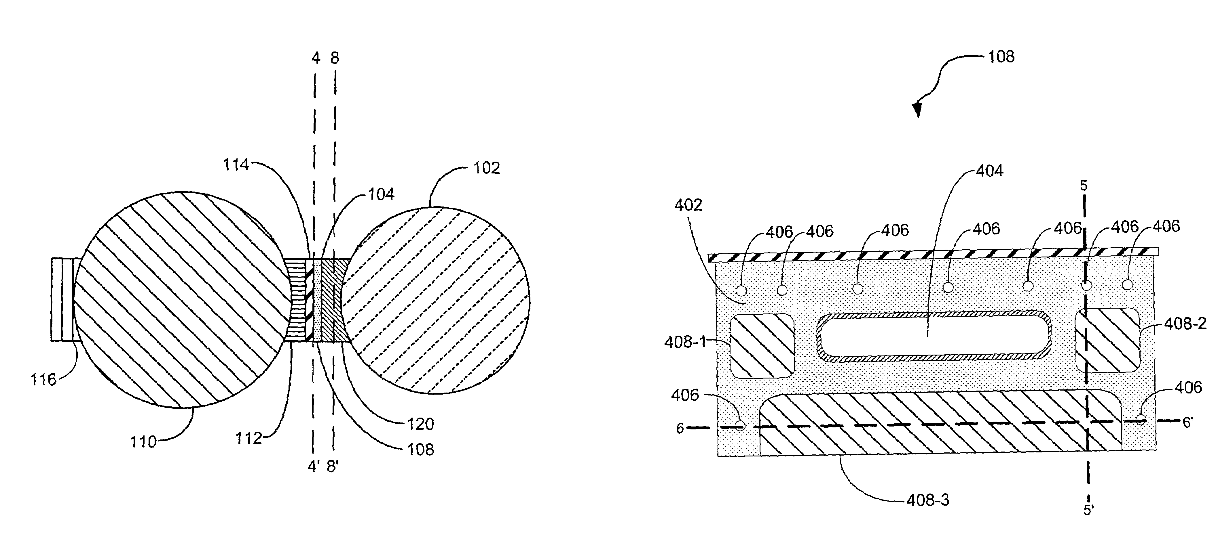
[0039]The present invention provides an improved apparatus for connecting two chambers in a closed environment. The improved apparatus minimizes heat transfer from the two chambers by including an improved interface. In some embodiments of the present invention, the improved interface is made of a material that has a reduced thermal conductivity coefficient. In other embodiments of the present invention, the interface includes one or more recesses so that the surface area between the interface and the second chamber is minimized. This surface area minimization reduces the amount of thermal energy that is transferred to the second chamber. In still other embodiments of the present invention, the apparatus includes a heating device to prevent heat loss near the aperture to the second chamber.

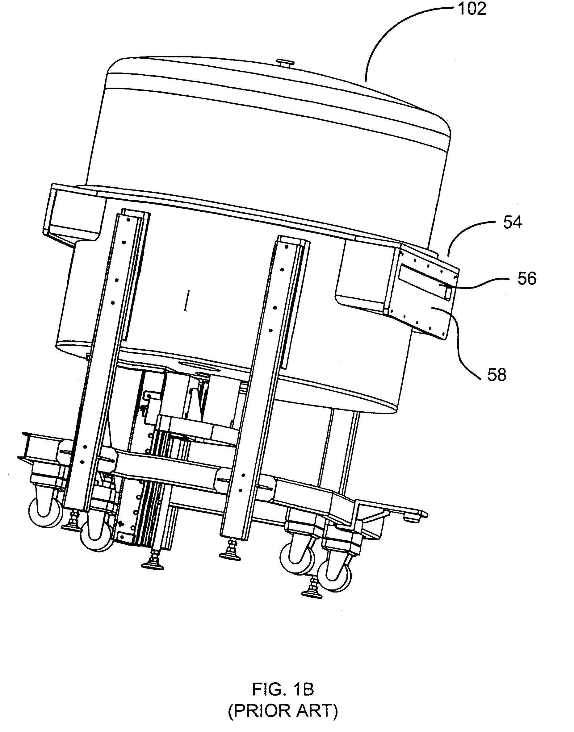
[0040]FIG. 1B discloses a conventional heat chamber 102 with a prior art apparatus 54 including a hole 56 through which substrates are passed between the conventional heat chamber 102 and a second...


PUM

PropertyMeasurementUnit
pressureaaaaaaaaaa
temperaturesaaaaaaaaaa

Abstract

An apparatus through which a substrate may be transferred between a first chamber and a second chamber in which the first chamber is maintained at a high temperature relative to the ambient temperature of the second chamber. The apparatus comprises a passageway for receiving the substrate and a thermally isolating interface. The thermally isolating interface reduces heat transfer from the first chamber to the second chamber and allows for transfer of the substrate between the apparatus and the second chamber. The thermally isolating interface includes a hole having dimensions such that the substrate is transferrable through the thermally isolating interface.

Description

[0001]This application is a continuation of U.S. patent application Ser. No. 09 / 891,784 filed Jun. 25, 2001 now abandoned, which is hereby incorporated by reference herein in its entirety.FIELD OF THE INVENTION[0002]The present invention generally relates to an apparatus through which a substrate may be transferred between a heat chamber and a second chamber, such as a central transfer chamber, to effect a semiconductor or glass substrate processing regimen. The present invention has application in a broad array of manufacturing processes, leading to improved semiconductors or flat panel display yields. Further, the invention also has application in prolonging the life of equipment used in such manufacturing processes.BACKGROUND[0003]Semiconductor devices are typically made in highly automated systems. Many of these systems include a central transfer chamber mounted on a monolithic platform. The central transfer chamber transfers semiconductor substrates to one or more specialized c...

Claims


Application Information

Patent Timeline
Patent Type & Authority Patents(United States)
IPC IPC(8): C23C16/00B65G29/00C23F1/00F27D3/00H01L21/306C23C16/54H01L21/00
CPCC23C16/54H01L21/67103Y10S414/139
Inventor BEER, EMANUELBAUMEL, KENNETH E.
Owner APPLIED MATERIALS INC
Why Eureka
Try Eureka