Electronic component housing structural body

a technology of electronic components and structural bodies, which is applied in the direction of electrical apparatus casings/cabinets/drawers, inorganic insulators, coupling device connections, etc., can solve the problems of generating a large amount of heat, affecting the stability of the electronic components, so as to facilitate the stable placement of the o-ring, facilitate the deformation into an elliptic shape, and ensure the effect of sealing

Inactive Publication Date: 2007-04-24
TOYOTA JIDOSHA KK +1
View PDF20 Cites 20 Cited by
  • Summary
  • Abstract
  • Description
  • Claims
  • Application Information

AI Technical Summary

Benefits of technology

[0019]According to the present invention, it is preferable that the sealing member for the electronic component housing structural body is an O-ring having a circular cross section. The O-ring can easily deform into an elliptic shape when the first and second housing bodies are coupled. Thus, the O-ring can assure reliable sealing properties for an inner clearance between the housing bodies.
[0020]Furthermore, it is preferable that the electronic component housing structural body further includes a grove formed on one sealing surface of the first and second housing bodies, wherein the O-ring is held in the groove. With this arrangement, the O-ring can be held stably in the groove formed on the sealing surface when the housing bodies are coupled. The groove can facilitate stable placing of the O-ring in position relative to the sealing surface when the housing bodies are coupled. Furthermore, the O-ring does not deform beyond the depth of the groove formed on the sealing surface. This surely prevents the O-ring from excessively deforming and accordingly eliminates the possibility of deteriorating the sealing properties due to excessive deformation of the O-ring.

Problems solved by technology

Electronic components and electronic units or assemblies accommodating numerous electronic components tend to generate a great amount of heat.
However, in the conventional electronic component housing structural body, various problems occur due to the use of FIPG that can assure sealing properties.
Applying the FIPG on the sealing surface(s) in the above-described manner takes a long time and requires an increased manufacturing lead time to accomplish the coupling of two housing bodies.
Furthermore, applying the FIPG on the sealing surface(s) places a heavy burden on workers and requires careful management with respect to the applying amount.
Thus, separation of the housing bodies is necessarily accompanied by troublesome work for removing or peeling the hardened FIPG off the sealing surfaces of the housing bodies.
Hence, the sealing surfaces may be scratched or damaged if the work is done roughly.
In such a case, the sealing surfaces possibly have scratches and water leakage may occur due to the scratches.
Thus, the housing bodies are no longer suitable to newly apply the FIPG on their sealing surfaces to connect the housing bodies again.
The total number of constituent components thus increases, and the manufacturing cost also increases.
Furthermore, disposing three O-rings on the sealing surface(s) is not practical in view of manufacturing workability.

Method used


Image

  • Electronic component housing structural body
  • Electronic component housing structural body
  • Electronic component housing structural body

Examples


Embodiment Construction

[0027]An embodiment of the present invention will be described below with reference to the drawings.

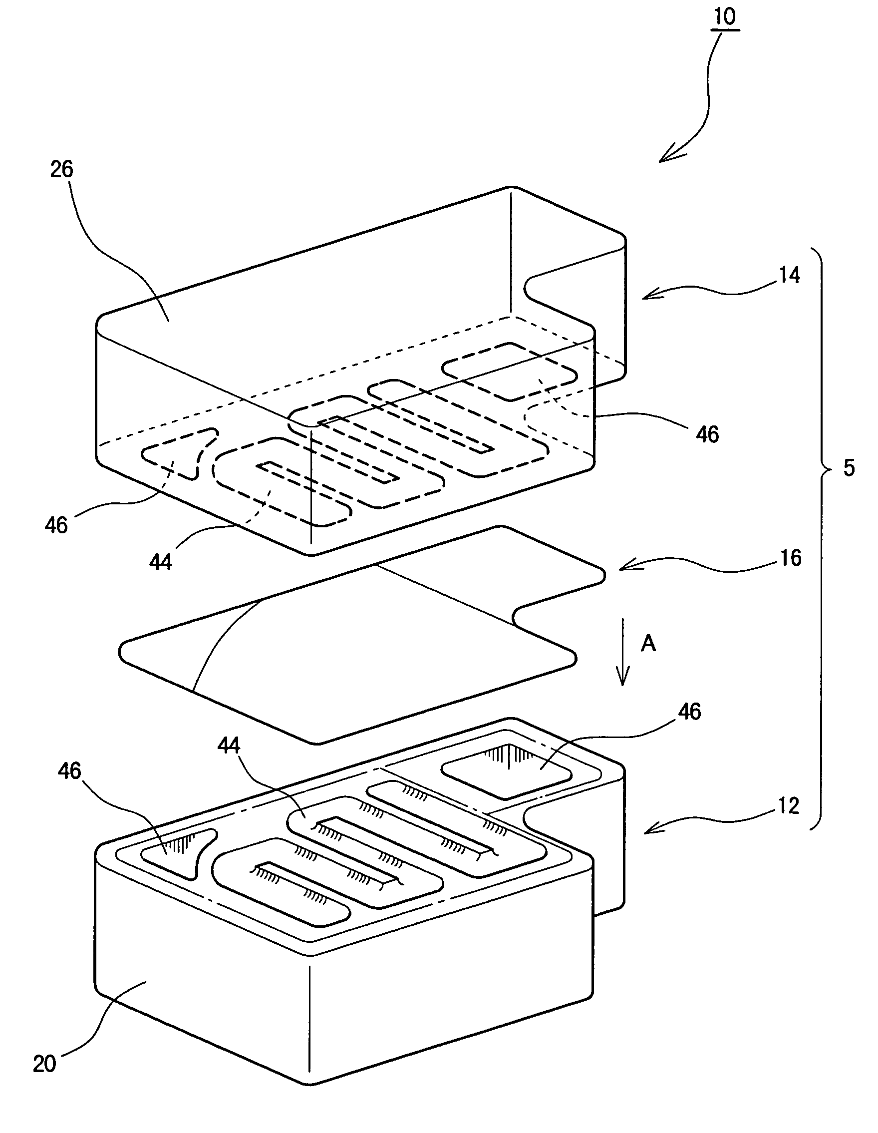
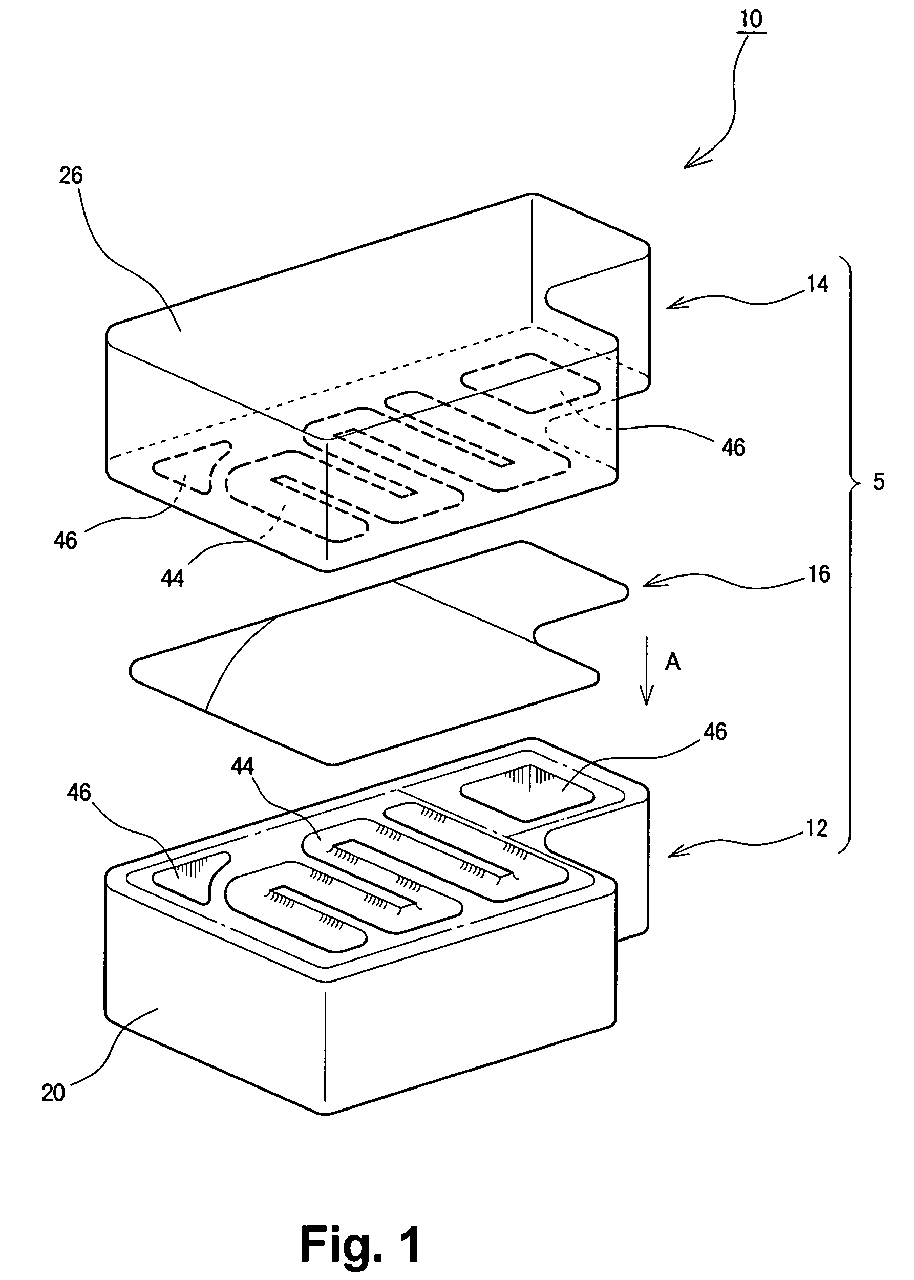
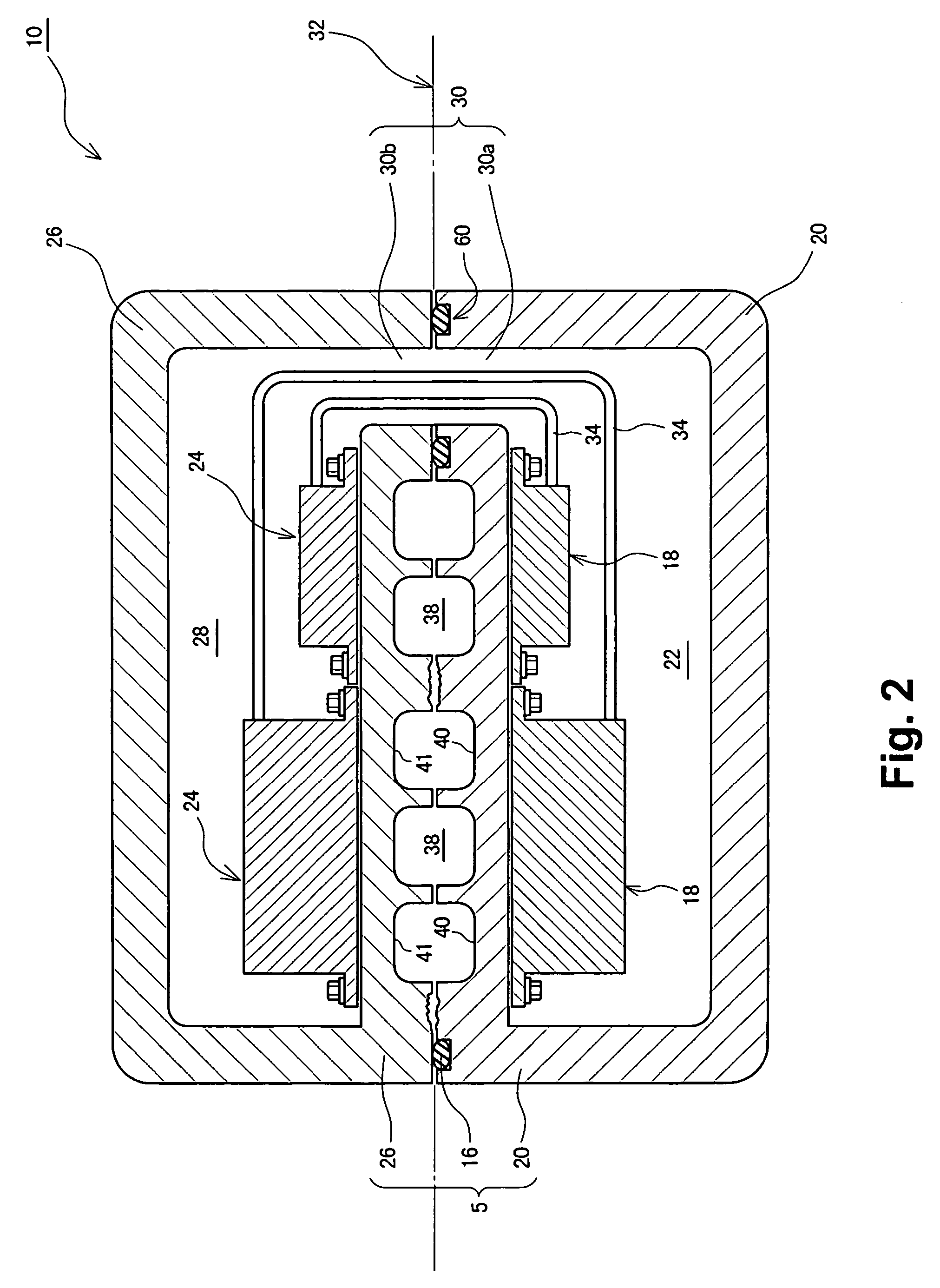
[0028]A power control unit 10 according to one embodiment of the present invention employs a structural body 5 that can accommodate electronic components. FIG. 1 is an exploded perspective view showing the power control unit 10, although only the external appearance of components is shown. FIG. 2 is a vertical cross-sectional view showing the power control unit 10. FIG. 3 shows a fitting plane of a converter housing body, seen from a direction of arrow A shown in FIG. 1.

[0029]The power control unit 10 functions as a device that can supply electrical power to a hybrid power plant (e.g., a combined electric motor / internal combustion engine) and can control an electrical power supply amount. As shown in FIG. 1, the power control unit 10 includes a boosting converter section 12 and a driving inverter section 14. The boosting converter section 12 can boost a DC voltage supplied from a batt...


PUM


Abstract

An electronic component housing structural body includes a first housing body accommodating electronic components and a second housing body accommodating electronic components. Fitting plane of the first and second housing bodies include a liquid passage area and a communicating passage area. The liquid passage area includes a cooling passage in which cooling liquid flows. The communicating passage area includes a communicating passage that connects housing chambers of the first and second housing bodies. Furthermore, a single sealing member is disposed on the fitting plane to independently surround and seal the liquid passage area and the communicating passage area.

Description

CROSS-REFERENCE TO RELATED APPLICATION[0001]The entire disclosure of Japanese Patent Application No. 2005-76460 including the specification, claims, drawings and abstract is incorporated herein by reference.BACKGROUND OF THE INVENTION[0002]1. Field of the Invention[0003]The present invention relates to a structural body accommodating electronic components, and more particularly to a sealing structure applied to a housing chamber in which electronic components are accommodated and also applied to a cooling passage formed in a structural body to cool the electronic component.[0004]2. Description of the Related Art[0005]Electronic components and electronic units or assemblies accommodating numerous electronic components tend to generate a great amount of heat. For example, an automotive vehicle equipped with a hybrid power plant (i.e., a combined electric motor / internal combustion engine) or an electric vehicle is subjected to a significant amount of heat generated from electronic comp...

Claims


Application Information

Patent Timeline
Patent Type & Authority Patents(United States)
IPC IPC(8): H02G3/08F16J15/10H02M7/48H05K7/20
CPCH05K7/20927H02M7/003H01L2924/0002H01L2924/00
Inventor SHINMURA, OSAMUUECHI, TATSUYUKI
Owner TOYOTA JIDOSHA KK
Why Eureka
Try Eureka