Constant-current battery charger

a battery charger and constant current technology, applied in electric power, electric vehicles, transportation and packaging, etc., can solve the problems of prolonging the time for reaching the target current, difficult to make a rapid increase of the charge current towards the target current, etc., and achieve the effect of increasing the charge curren

Active Publication Date: 2007-04-24
MATSUSHITA ELECTRIC WORKS LTD
View PDF6 Cites 19 Cited by
  • Summary
  • Abstract
  • Description
  • Claims
  • Application Information

AI Technical Summary

Benefits of technology

[0005]In view of the above insufficiency, the present invention has been achieved to provide a constant-current battery charger which is capable of increasing the charge current rapidly to the target current for assuring a rapid charging successfully.
[0006]The battery charger in accordance with the present invention includes a power supply configured to supply a charge current to a secondary cell, and a current monitor configured to monitor a charge current being supplied to the cell and give a current signal indicative of the charge current. A controller is included to control the power supply for varying the charge current in accordance with the current signal from the current monitor. The controller calculates a current difference between a predetermined target current and the charge current being monitored, and generates a demand of varying the charge current at a first charge rate when the current difference is out of a predetermined range, and varying the charge current at a second charge rate when the current difference is within the predetermined range. The controller generates the demand repeatedly at regular or varying intervals for varying the charge current. The first charge rate is set to be higher than the second charge rate in order to make a rapid charging until it comes close to the target current. Since the current difference between the instant charge current and the target current is relied upon to switch the charge rate between the first and second charge rates, the switching can be made at an exact timing truly indicative of the condition of the battery, which enables a rapid charging, yet assuring to complete the charging successfully. In fact, since the switching of the charge rate is dependent upon the current difference, the charging can be free from being influenced by uncertain characteristic changes which would arise at a transition from the high-rate charging to the low-rate charging when, for example, the cell voltage is relied upon for the switching.
[0012]Preferably, the controller is configured to inhibit the power supply from providing the charge current when the charge current goes beyond an upper limit while varying the charge current at the first charge rate. Thus, the charger as well as the secondary cell can be protected from unduly high current which might destroy the charger and the cell.

Problems solved by technology

Accordingly, the above constant-charging scheme is, in principle, difficult to make a rapid increase of the charge current towards the target current when there is a considerable difference therebetween.
However, since a charge current may be deviated largely from the target current during the constant-voltage charging, there remains a problem that the target current is not expected to be rapidly reached as long as the constant-voltage charging is made, which eventually prolongs a time for reaching the target current.

Method used


Image

  • Constant-current battery charger
  • Constant-current battery charger
  • Constant-current battery charger

Examples


Embodiment Construction

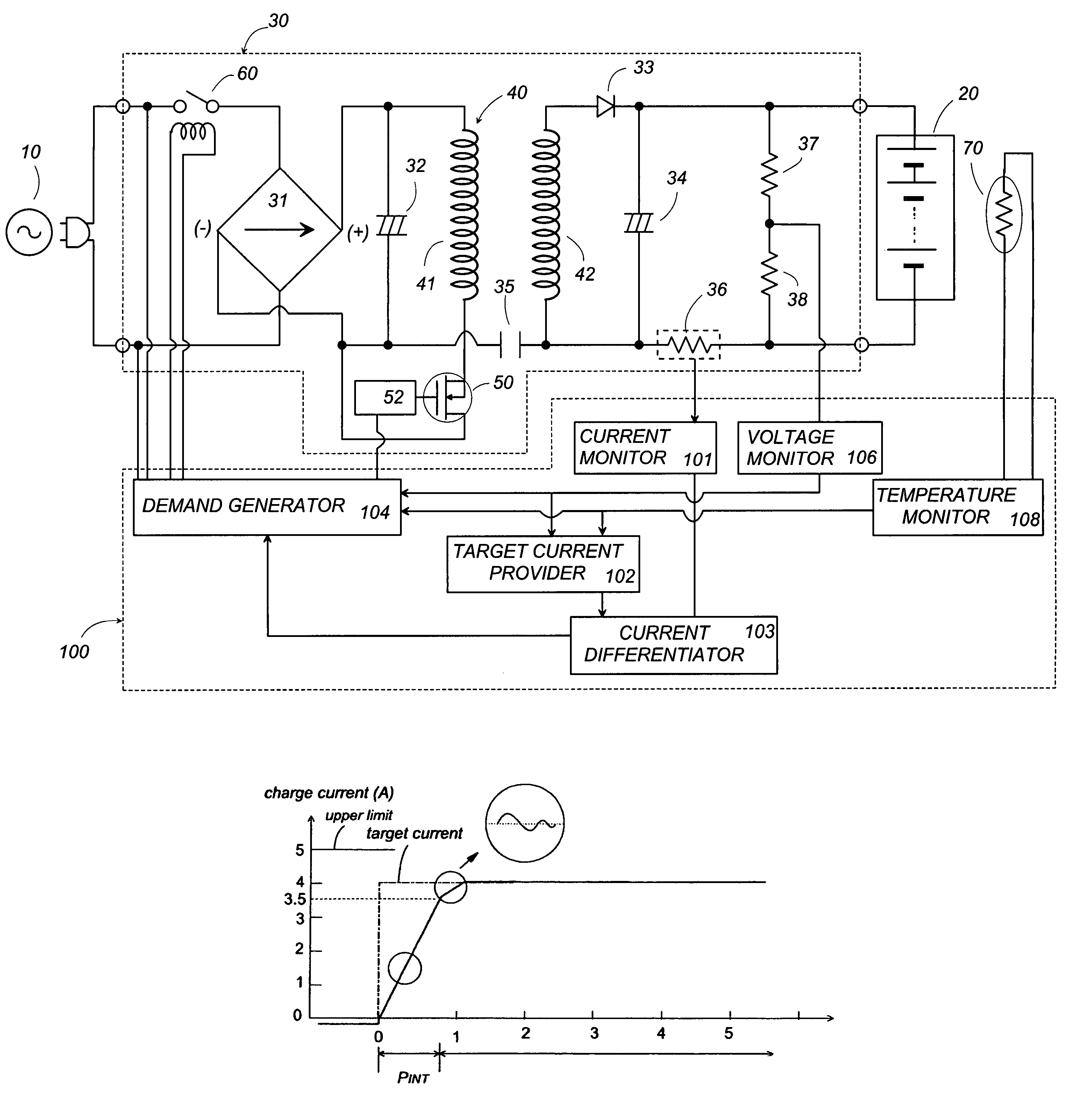
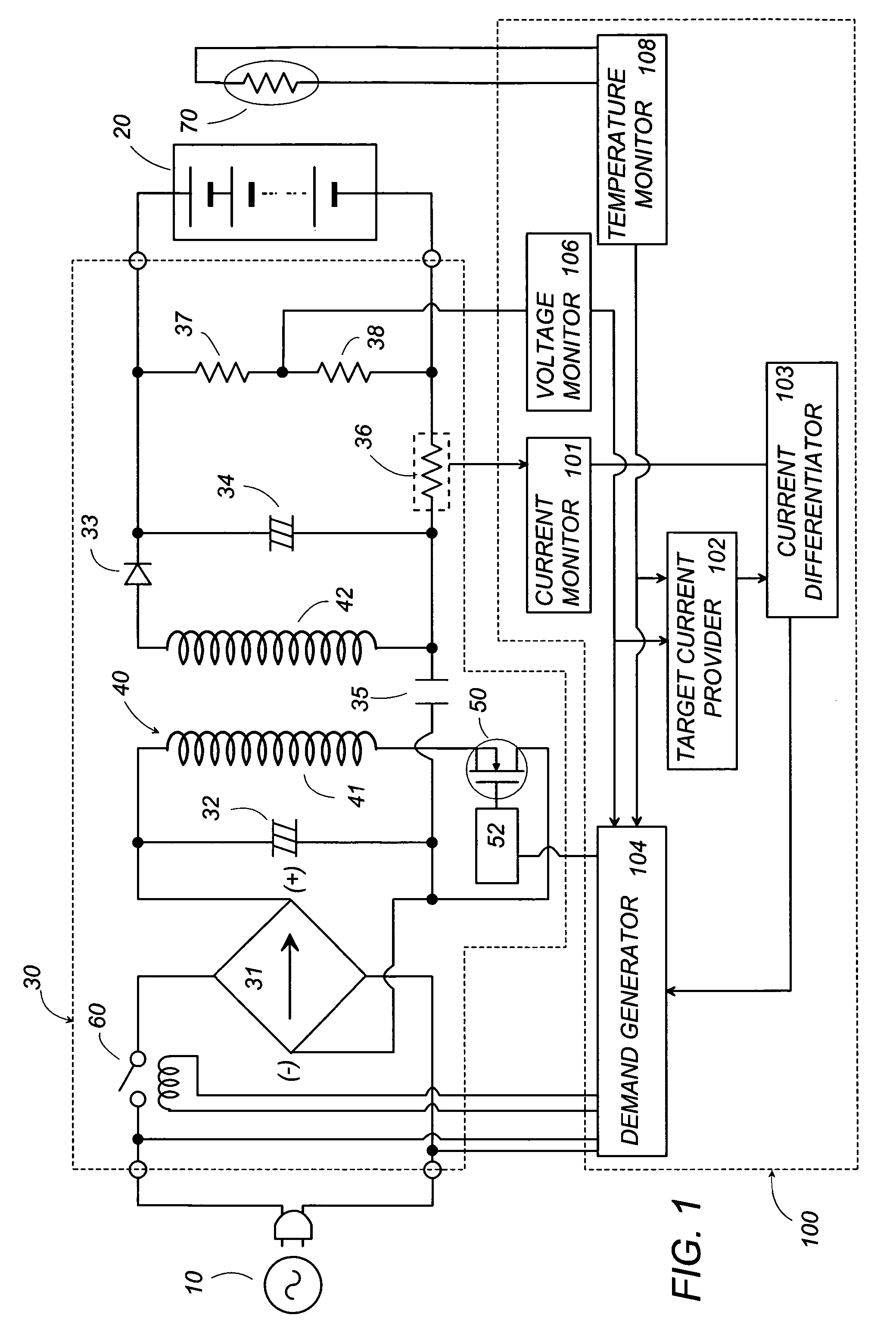
[0020]Referring now to FIG. 1, there is shown a battery charger in accordance with a preferred embodiment of the present invention. The battery charger includes a power supply 30 configured to receive an AC voltage from an AC power source 10 and convert it into a DC voltage for supplying a charge current for recharging a secondary cell 20. The power supply 30 includes a rectifier 31 in the form of a diode bridge providing a rectified DC voltage which is then smoothed by a capacitor 32 connected across the output of the rectifier 31. Also included in power supply 30 is a transformer 40 with a primary winding 41 connected across the output of the rectifier 31, and with a secondary winding 42 connected across the secondary cell 20. A switching element 50, for example, FET is connected in series with the primary winding 41 across the outputs of the rectifier 31 in order to periodically interrupt the smoothed DC voltage at a high frequency to induce a corresponding AC voltage across the ...


PUM


Abstract

A constant-current battery charger includes a power supply for supplying a charge current to a secondary cell, and a current monitor for monitoring a charge current being supplied to the cell. A controller is included for varying the charge current in accordance with the monitored charge current. The controller calculates a current difference between a predetermined target current and the instant charge current, and generates a demand of varying the charge current at a first charge rate when the current difference is out of a predetermined range, and varying the charge current at a second charge rate when the current difference is within the predetermined range. The controller generates the demand repeatedly at regular or varying intervals for varying the charge current. The first charge rate is set to be higher than the second charge rate in order to make a rapid charging until it comes close to the target current. Since the current difference between the instant charge current and the target current is relied upon to switch the charge rate between the first and second charge rates, the switching can be made at an exact timing truly indicative of the condition of the battery, which enables a rapid charging, yet assuring to complete the charging successfully.

Description

TECHNICAL FIELD[0001]The present invention relates to a constant-current battery charger for charging a secondary cell.BACKGROUND ART[0002]Secondary cells or rechargeable batteries have been widely utilized in power tools, cellular phones, and many other portable electrical devices. In order to charge the cells such as nickel-cadmium batteries and nickel-hydrogen batteries, it has been proposed a constant-current battery charger which supplies a relatively uniform current to the cells. Normally, the constant-charging repeats a cycle of monitoring the charge current being supplied to the cells, comparing the monitored charge current with a target current, and varying the charge current at a uniform charge rate to regulate the current in match with the target current. Therefore, when charging almost exhausted cells, a large number of the above cycles have to be repeated until the charge current comes close to the target current.[0003]The charge rate is selected to a relatively low in ...

Claims


Application Information

Patent Timeline
Patent Type & Authority Patents(United States)
IPC IPC(8): H02J7/00
CPCH02J7/0072H02J7/06H02J7/00711H02J7/00714H02J7/007182H02J7/007194
Inventor KUBOTAMIWAIKEDA, MASAKISHIMIZU
Owner MATSUSHITA ELECTRIC WORKS LTD
Why Eureka
Try Eureka