RF-energy modulation system through dynamic coil detuning

a dynamic coil and energy modulation technology, applied in the field of implantable medical devices, can solve the problems reducing the power drawn from the master device, and reducing so as to reduce the energy reduce the coupling, and reduce the effect of limiting the power received by the slave devi

Active Publication Date: 2007-04-24
BOSTON SCI NEUROMODULATION CORP
View PDF13 Cites 104 Cited by
  • Summary
  • Abstract
  • Description
  • Claims
  • Application Information

AI Technical Summary

Benefits of technology

[0012]In accordance with one aspect of the invention, there is provided a detuning circuit corresponding to each power reception circuit of each slave device. The slave devices receive power from a single master device through inductive coupling of a primary coil in the master device with secondary coils in the slave devices. The power transferred through the inductive coupling is proportional to the coil separation distance to the sixth power. Thus, the slave devices near the master device receive significantly more power than slave devices farther from the master device, and may over heat. The energy reception is also related to how well the power reception circuit is tuned to the resonant frequency of the primary coil. The detuning circuit monitors the power received by the slave devices, and detunes the power reception circuit from the primary coil when the power level exceeds a threshold, thereby reducing the energy received by the slave devices.
[0013]It is a feature of the invention that the detuning circuit reduces the coupling between the primary coil in the master device and the power reception circuit in the slave device. Known master devices are battery powered, and the life of the battery is an important feature of such master device. The master device provides power to implantable slave devices over an inductive link, and the power drawn from the master device by such inductive link is related to the magnetic coupling between the primary and secondary coils and the matching factor of the transmitting and receiving circuits. Advantageously, limiting power received by the slave devices, by reducing the matching factor between the master device and the slave devices, reduces the power drawn from the master device, and extends battery life.
[0014]It is an additional feature of the present invention to provide a controlled range of voltages to battery charging circuits within the implantable slave devices. The battery charging circuit is adapted to provide the correct power to the battery for effective charging. However, when the voltage provided to the charging circuit is higher than the battery charging voltage, power is dissipated within the charging circuit to achieve the necessary voltage reduction. Such power dissipation results in the generation of heat within the charging circuit, and a reduction of the life of the charging circuit. By controlling the range of voltage provided to the charging circuit, the present invention reduces the power dissipated within the charging circuit, and extends the life of the charging circuit.

Problems solved by technology

Thus, the slave devices near the master device receive significantly more power than slave devices farther from the master device, and may over heat.
Advantageously, limiting power received by the slave devices, by reducing the matching factor between the master device and the slave devices, reduces the power drawn from the master device, and extends battery life.
However, when the voltage provided to the charging circuit is higher than the battery charging voltage, power is dissipated within the charging circuit to achieve the necessary voltage reduction.
Such power dissipation results in the generation of heat within the charging circuit, and a reduction of the life of the charging circuit.

Method used


Image

  • RF-energy modulation system through dynamic coil detuning
  • RF-energy modulation system through dynamic coil detuning
  • RF-energy modulation system through dynamic coil detuning

Examples


Embodiment Construction

[0026]The following description is of the best mode presently contemplated for carrying out the invention. This description is not to be taken in a limiting sense, but is made merely for the purpose of describing the general principles of the invention. The scope of the invention should be determined with reference to the claims.

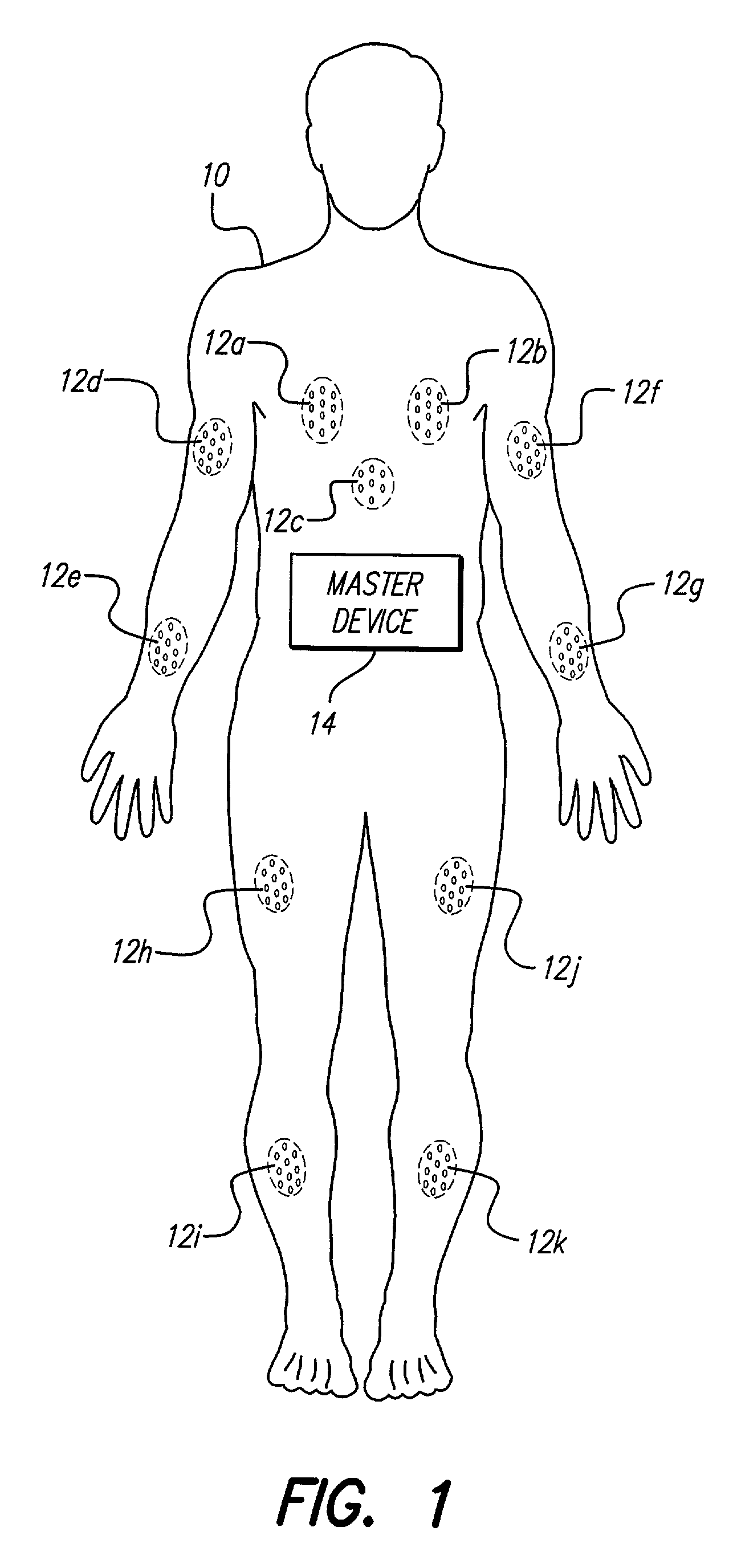
[0027]A Functional Electrical Stimulation (FES) system generates electrical signals to stimulate nerves and muscles to provide movement for paraplegics, quadriplegics, and other individuals with a neural lesion, a neuro degenerative disease, or other physical condition depriving the patient of the use of the muscles. Similarly, heart or lung muscles may be stimulated to provide the appropriate blood flow and oxygen for various activities, and various sensors may be implanted to monitor body functions. A master device 14 of an FES system centrally carried on a patient 10 is shown in FIG. 1. The master device 14 includes a primary antenna to transmit power and...


PUM


Abstract

An RF-energy modulation system dynamically adjusts tuned receiving circuits within a plurality of slave devices, thereby regulating the level of power reception in each slave device. The slave devices receive power from a single master device, through coupling of a primary antenna in the master device with a secondary antenna in each slave device. The amount of the power received by each slave device is a function of the antenna separation distance, and is thus different at each slave device location. The RF-energy modulation system monitors the power requirements of the slave device within which the modulation system is included, and modulates the tuning of the secondary antenna to maintain the proper power reception level. Advantageously, such modulation controls the power reception by the slave device, versus dissipating energy already received by the slave device. In a preferred embodiment, the RF-energy modulation system controls the power received by a multiplicity of microstimulators implanted in a single patient.

Description

[0001]The present application claims the benefit of U.S. Provisional Application Ser. No. 60 / 293,302, filed May 24, 2001, which application is incorporated herein by reference.BACKGROUND OF THE INVENTION[0002]The present invention relates to implantable medical devices and more particularly to an improvement to known methods for providing power from a single external device to a multiplicity of implantable microstimulators implanted within the same patient. Known implantable microstimulators receive power inductively from an external device. The improvement provided by the present invention dynamically adjusts the power reception of individual microstimulators to compensate for differences in the separation of each microstimulator from the external device.[0003]Implantable microdevices have the potential to address a number of useful purposes. These purposes range from pain mitigation to Functional Electrical Stimulation (FES). Some of these applications require that a multiplicity ...

Claims


Application Information

Patent Timeline
Patent Type & Authority Patents(United States)
IPC IPC(8): A61N1/08
CPCA61N1/3787A61N1/37205
Inventor PARRAMON, JORDIMARNFELDT, GORAN N.
Owner BOSTON SCI NEUROMODULATION CORP
Why Eureka
Try Eureka