Locomotive location system and method

Inactive Publication Date: 2007-04-24
AUSTRALIAN RAIL TRACK CORP
View PDF12 Cites 19 Cited by
  • Summary
  • Abstract
  • Description
  • Claims
  • Application Information

AI Technical Summary

Benefits of technology

[0013]It is another objective of the present invention to provide a method for along-track position determination of sufficient accuracy to enable turnout detection in the necessary timely manner discussed above.

Problems solved by technology

A problem arises, for example, when testing is too early or too late relative to the event of pulling a train onto a siding as this results in erroneously concluding the train remained on the mainline; this issue is the case even for otherwise flawless turnout detection logic since the duration of the event may be quite small for even moderate speeds of travel, e.g. 45 mph.

Method used


Image

  • Locomotive location system and method
  • Locomotive location system and method
  • Locomotive location system and method

Examples


Embodiment Construction

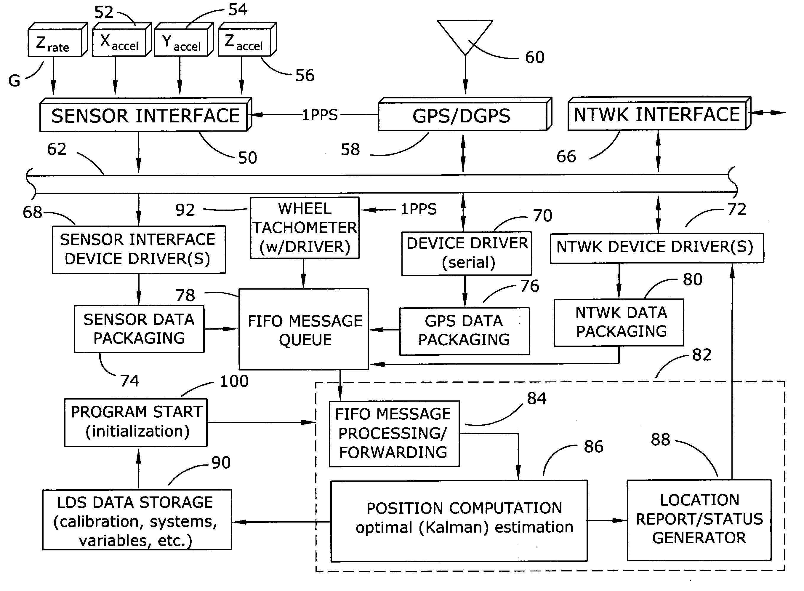
[0031]The present invention provides the methods described above by implementing the process of FIG. 11 including a track profile model TPM, an inertial measurement unit IMU, a navigation module NAVM, exogenous measurement data input (i.e. data originating externally of the device) and corresponding model EXOM thereof, non-exogenous null pseudo-measurement data and corresponding model of physical constraints imposed thereof, and an optimal estimator OEST.

[0032]The track profile model TPM is used to represent, continuously as a function of the along-track position, the track centerline profile and includes a set of interpolation formulas (viz., for each of the centerline profile angles of latitude, longitude, grade, super-elevation, and heading) required to align an earth-fixed reference frame to a rail reference frame coincident with the track centerline and level across the two rails. The interpolation formulas require a discrete number of input parameters, referred to herein as tr...


PUM


Abstract

A locomotive location system and method utilizes inertial measurement inputs, including orthogonal acceleration inputs and turn rate information, in combination with wheel-mounted tachometer information and GPS / DGPS position fixes to provide processed outputs indicative of track occupancy, position, direction of travel, velocity, etc. Various navigation solutions are combined together to provide the desired information outputs using an optimal estimator designed specifically for rail applications and subjected to motion constraints reflecting the physical motion limitations of a locomotive. The system utilizes geo-reconciliation to minimize errors and solutions that identify track occupancy when traveling through a turnout.

Description

CROSS-REFERENCE TO RELATED APPLICATION[0001]This application is a continuation-in-part of commonly owned U.S. patent application Ser. No. 10 / 700,044 filed Nov. 4, 2003 (now abandoned) which, in turn, is a continuation-in-part of commonly owned U.S. patent application Ser. No. 10 / 041,744 filed Jan. 10, 2002, now U.S. Pat. No. 6,641,090.BACKGROUND OF THE INVENTION[0002]Various systems have been developed to track the movement of and location of railway trains on track systems.[0003]In its simplest form, train position can be ascertained at a central control facility by using information provided by the crew, i.e., the train crew periodically radios the train position to the central control facility; this technique diverts the attention of the crew while reporting the train position, often requires several “retries” where the radio link is intermittent, and the position information rapidly ages.[0004]Early efforts have involved trackside equipment to provide an indication of the locati...

Claims


Application Information

Patent Timeline
Patent Type & Authority Patents(United States)
IPC IPC(8): G01C21/26B61L25/02
CPCB61L25/021B61L25/023B61L25/025B61L25/026B61L25/028B61L2205/04
Inventor MEYER, THOMAS J.METZGER, THOMAS R.
Owner AUSTRALIAN RAIL TRACK CORP
Why Eureka
Try Eureka