Oxidation catalyst coating in a heat exchanger

a heat exchanger and catalyst technology, applied in the direction of indirect heat exchangers, machines/engines, lighting and heating apparatus, etc., can solve the problems of reducing affecting the efficiency of heat removal, and affecting the performance of heat removal

Active Publication Date: 2007-05-01
INT ENGINE INTPROP CO LLC
View PDF19 Cites 42 Cited by
  • Summary
  • Abstract
  • Description
  • Claims
  • Application Information

AI Technical Summary

Problems solved by technology

In other cases, heat may be undesirable and removed by use of other components and systems.
Even though heat input may be desirable for some engine systems, heat removed from other systems that is typically rejected back to the engine is undesirable.
EGR Coolers may become “fouled” as a result and lose heat transfer effectiveness and flow area.
EGR valves can become fouled with deposits and become inoperable or sluggish.
A disadvantage of this approach is that the catalytic oxidation of pollutants in the EGR exhaust stream releases heat.

Method used


Image

  • Oxidation catalyst coating in a heat exchanger
  • Oxidation catalyst coating in a heat exchanger
  • Oxidation catalyst coating in a heat exchanger

Examples


Embodiment Construction

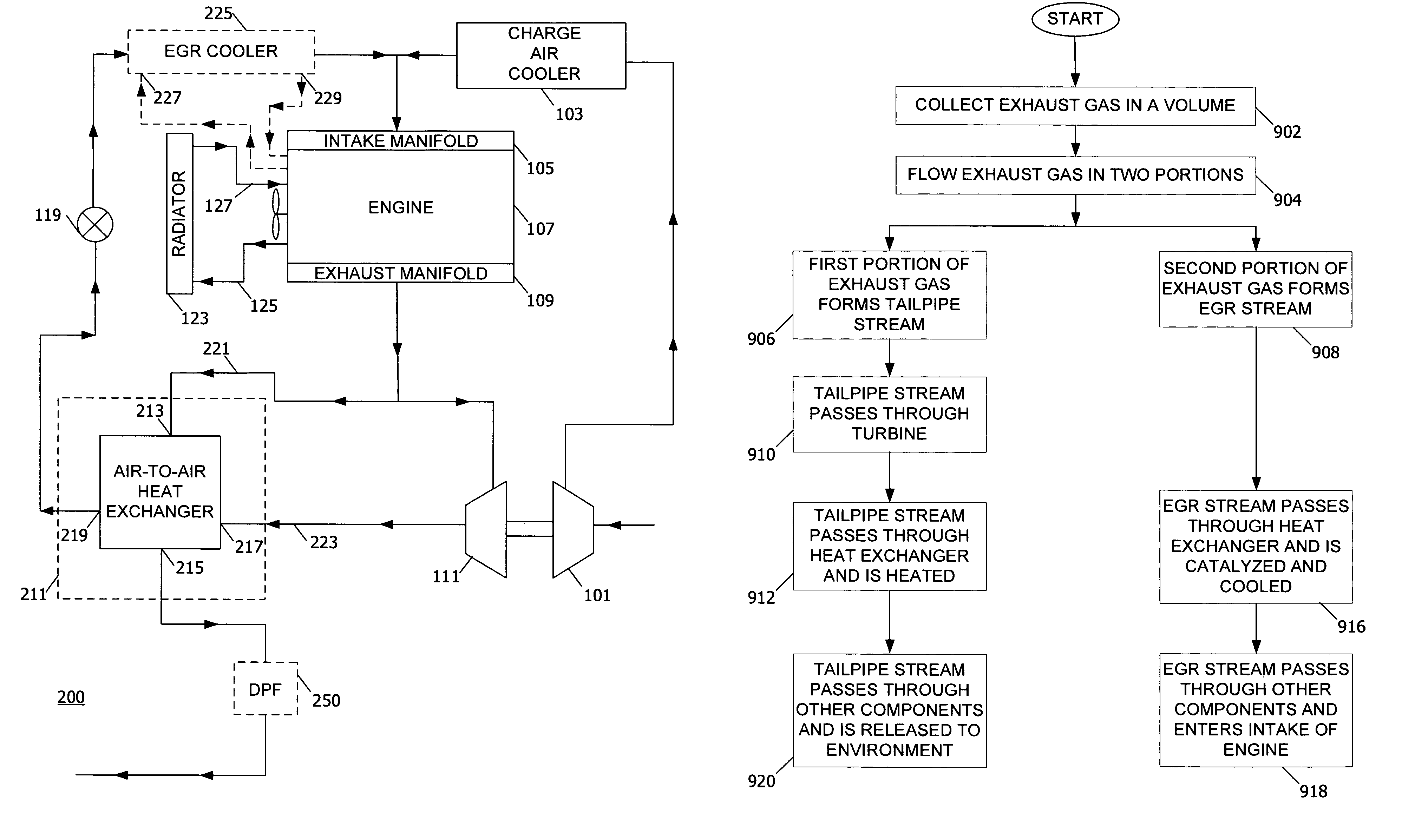
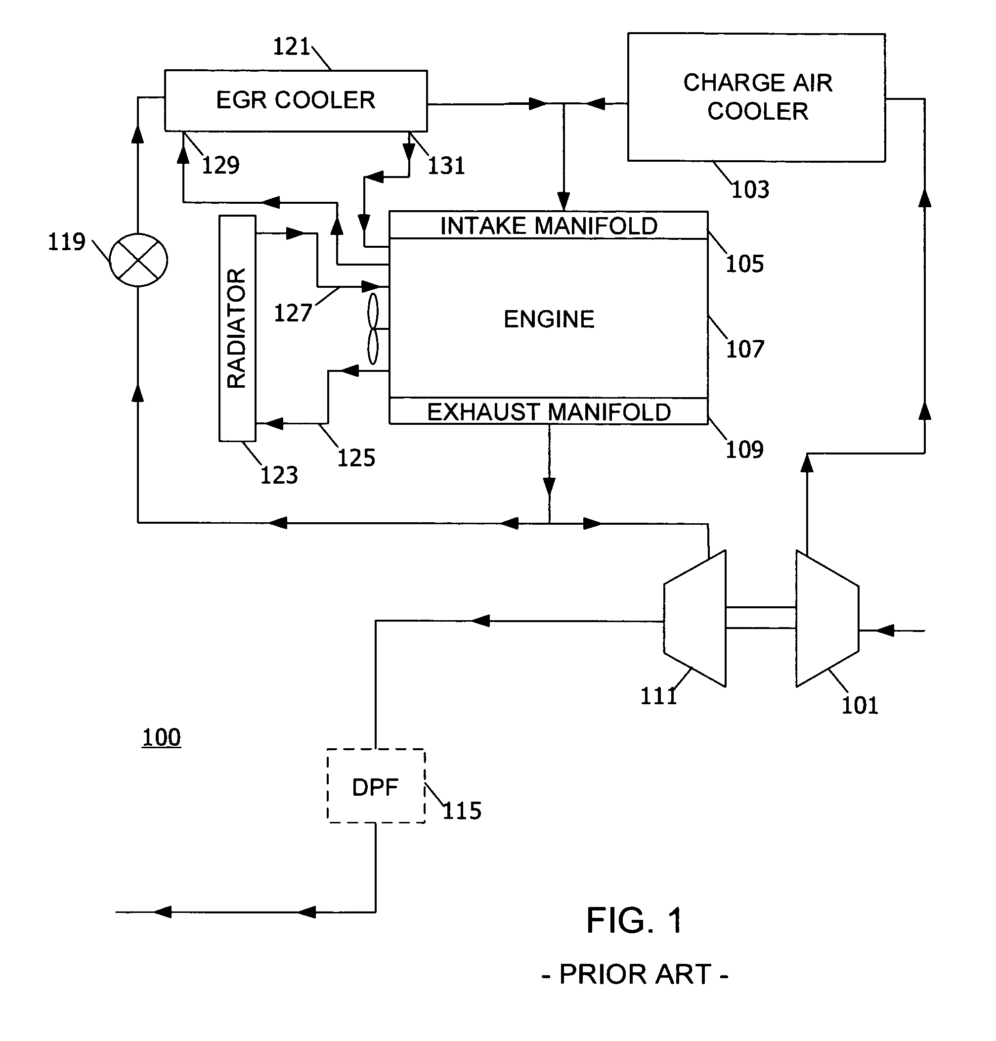
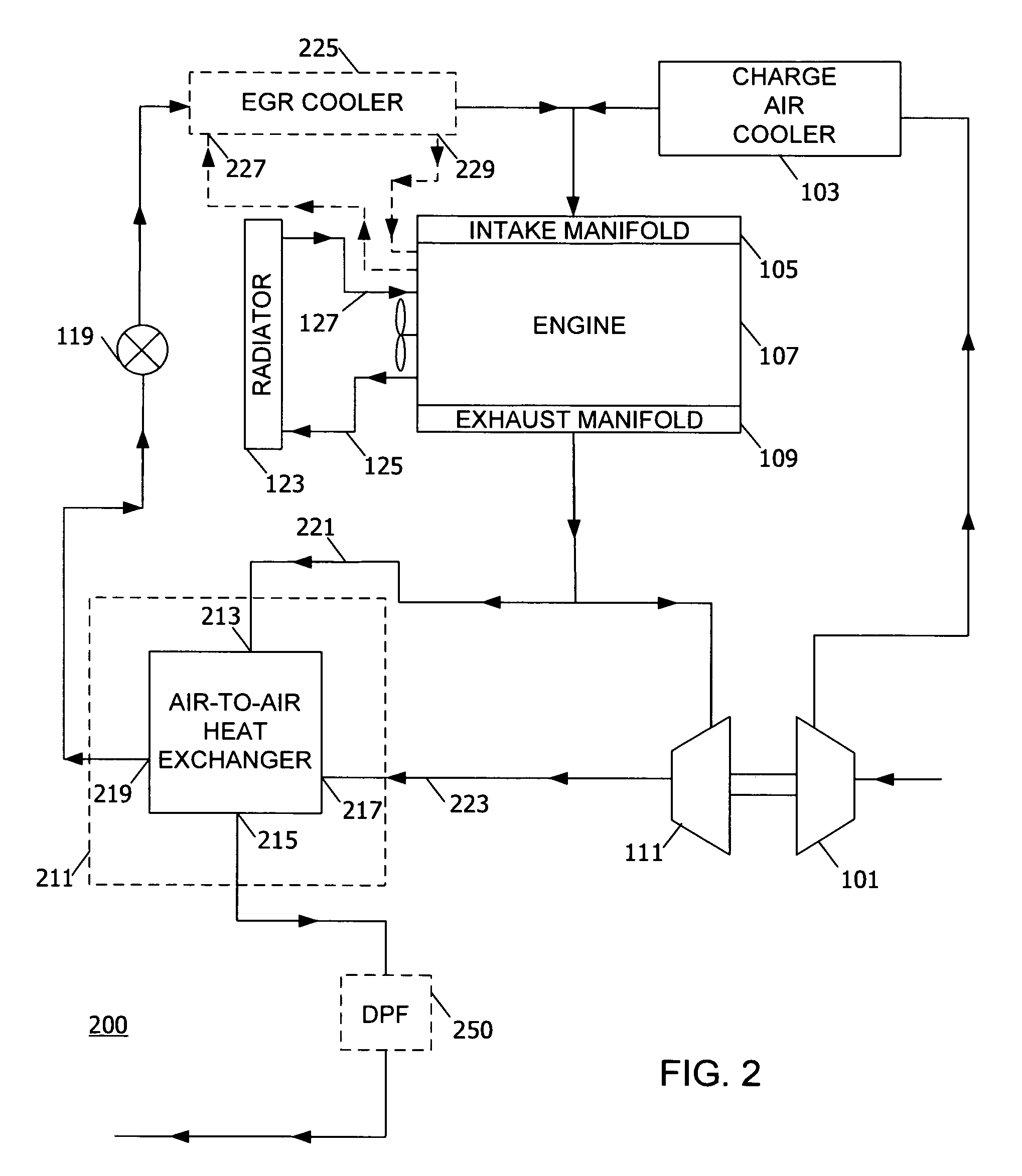
[0021]The following describes an apparatus for and method of reducing undesirable heat load for a cooling system of an internal combustion engine. A typical turbocharged diesel engine system 100 having cooled EGR is shown in FIG. 1. Fresh air enters a compressor 101 of an engine 107. An outlet of the compressor 101 is connected to a charge air cooler 103. An outlet of the charge air cooler 103 is connected to an intake manifold 105 of an engine 107. Compressed air enters a combustion chamber through the intake manifold 105 of the engine 107, where it is mixed with fuel. The mixture of air and fuel is compressed in the combustion chamber and combusts releasing work and heat. Heat released from the combustion of fuel and air is removed from the engine 107 in two ways. First, fluids such as oil and / or water-based coolants are circulated through the engine 107, in direct contact with engine components.

[0022]As engine components heat up, fluid circulating through the engine 107 is heated...


PUM


Abstract

A method for an internal combustion engine includes the steps of collecting exhaust gas in a volume (902) and flowing exhaust gas out of the volume in a first and a second portions (904). The first portion forms a tailpipe gas stream (906), and the second portion forms an EGR gas stream (908). The tailpipe gas stream goes through a turbine (910). The EGR gas stream is catalyzed by an oxidizer coating in a heat exchanger, and thermal energy is transferred from the EGR gas stream to the tailpipe stream in the heat exchanger (916).

Description

CLAIM OF PRIORITY[0001]This application is a continuation-in-part application of and claims the priority benefit of the filing date of Non-Provisional application Ser. No. 11 / 256,916 filed Oct. 24, 2005, on behalf of the same inventor as the present application and assigned to the assignee hereof.FIELD OF THE INVENTION[0002]This invention relates to internal combustion engines, including but not limited to engines having exhaust gas heat exchangers.BACKGROUND OF THE INVENTION[0003]Internal combustion engines generate heat during operation that is released into the environment through exhaust gas emissions. Modern emission controls systems may utilize energy, in the form of heat from the exhaust gas, to operate various components, for example, Diesel Particulate Filters (DPF). In other cases, heat may be undesirable and removed by use of other components and systems.[0004]One example of a case where additional heat is desirable for the operation of an engine is the operation of a DPF...

Claims


Application Information

Patent Timeline
Patent Type & Authority Patents(United States)
IPC IPC(8): F02M25/07F02B33/44F02B47/08
CPCF01N3/0205F02B37/00F02M25/0718F02M25/0728F02M25/0732F02M25/0737F28D7/106F01N2240/02F02B29/0406F02M25/0707Y02T10/121Y02T10/144Y02T10/20F28F2240/00F02M26/05F02M26/15F02M26/25F02M26/24F02M26/32F02B47/08Y02T10/12
Inventor SAELE, GREGORY J.
Owner INT ENGINE INTPROP CO LLC
Why Eureka
Try Eureka