Vehicular drive system

a technology of drive system and drive shaft, which is applied in the direction of mechanical actuated clutches, propulsion using engine-driven generators, transportation and packaging, etc., can solve the problems of reducing the stirring resistance of oil, and achieve the effect of minimizing the loss of driving for

Active Publication Date: 2007-05-01
HONDA MOTOR CO LTD
View PDF6 Cites 27 Cited by
  • Summary
  • Abstract
  • Description
  • Claims
  • Application Information

AI Technical Summary

Benefits of technology

[0006]The present invention has been achieved under the above-mentioned circumstances, and it is an object thereof to minimize the loss in driving force due to motor drag resistance and oil stirring resistance during travel of a vehicle having at least a motor as a drive source for travel.
[0008]In accordance with this arrangement, since the motor isolation means isolates the motor from the power transmission mechanism when the driving force of the motor is not needed, it is possible to eliminate the motor drag resistance, and moreover there is no possibility that the motor will excessively rotate even if the vehicle travels at high speed. Furthermore, accompanying the isolation of the motor, the oil retaining means retains within the motor case a portion of the oil within the casing of the power transmission mechanism, and thus it is possible to lower the oil level within the casing of the power transmission mechanism, thus reducing the oil stirring resistance. Since the motor is stopped at this time, even if the oil level within the motor case increases, the oil stirring resistance to a rotor of the motor will not increase.
[0010]Therefore, by isolating the motor from the power transmission mechanism, it is possible to automatically lower the oil level within the casing of the power transmission mechanism.
[0011]Moreover, in accordance with a third aspect of the present invention, in addition to the first aspect, the motor isolation means is a hydraulic clutch, and the oil retaining means is operated by hydraulic pressure for engaging and disengaging the hydraulic clutch. Therefore, by isolating the motor from the power transmission mechanism, it is possible to automatically lower the oil level within the casing of the power transmission mechanism.
[0013]In accordance with this arrangement, since the driving forces of the engine and the motor are transmitted to the driven wheels via the transmission, when the vehicle travels by the driving force of the engine or by inertia, the oil stirring resistance within the casing of the transmission can be reduced.
[0015]In accordance with this arrangement, since the driving force of the motor is distributed between the left and right driven wheels via the differential gear, when the vehicle is made to travel by a drive source other than the motor or inertia, the oil stirring resistance within the casing of the differential gear can be reduced.

Problems solved by technology

Furthermore, accompanying the isolation of the motor, the oil retaining means retains within the motor case a portion of the oil within the casing of the power transmission mechanism, and thus it is possible to lower the oil level within the casing of the power transmission mechanism, thus reducing the oil stirring resistance.

Method used


Image

  • Vehicular drive system
  • Vehicular drive system
  • Vehicular drive system

Examples


first embodiment

[0052]The operation of the present invention having the above-mentioned arrangement is now explained.

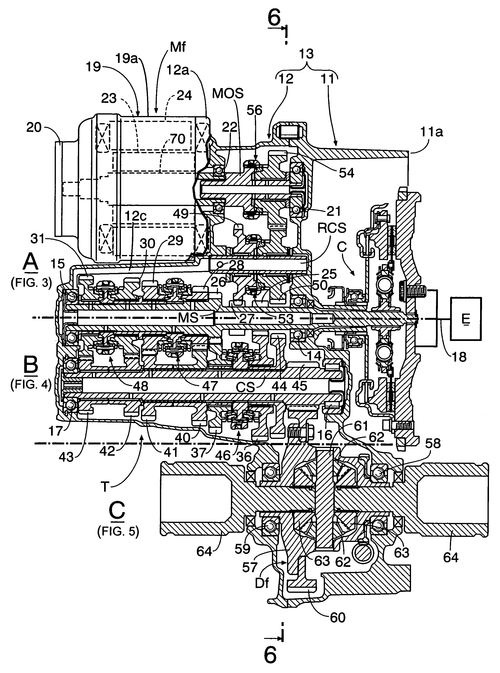
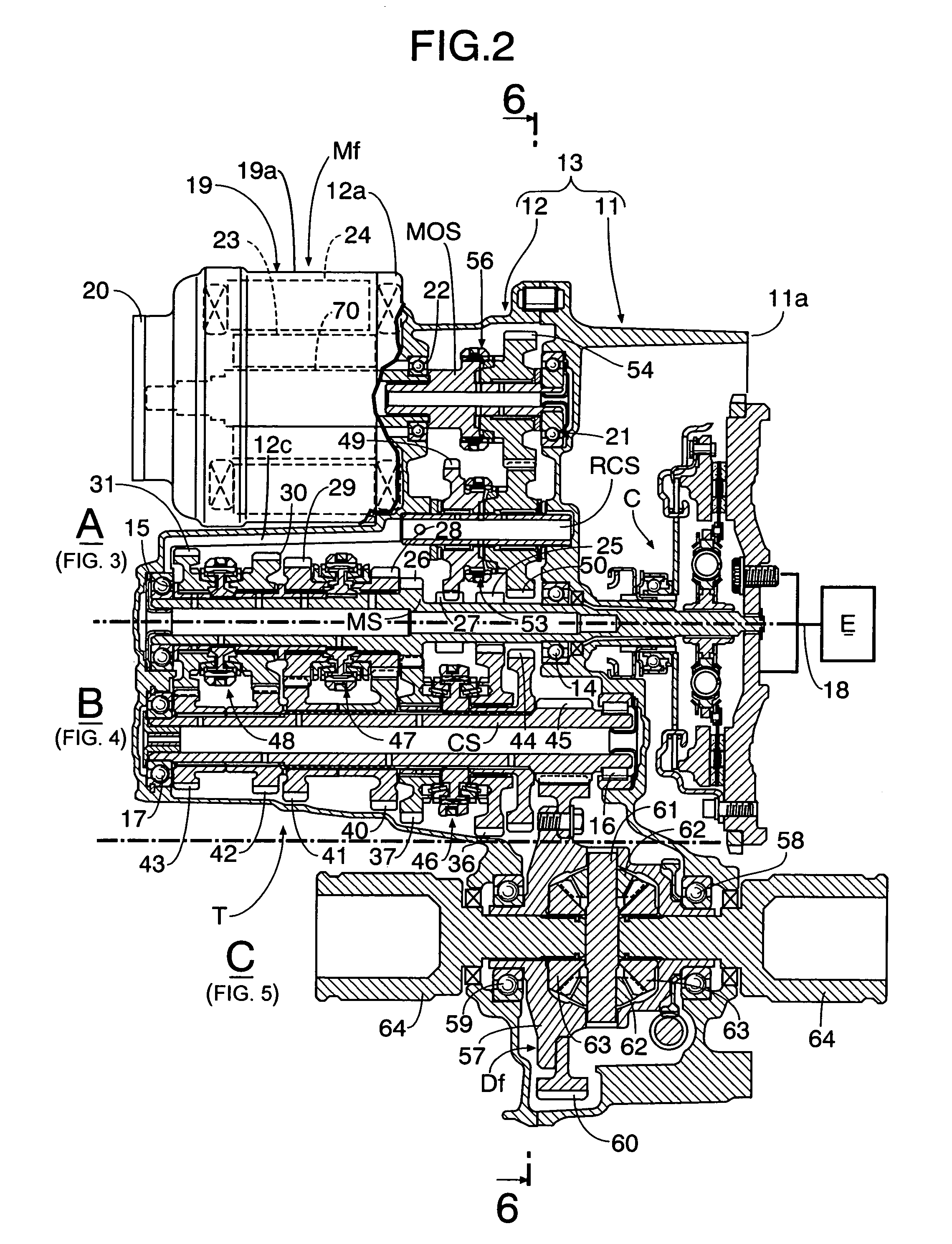
[0053]When the vehicle travels forward by means of the engine E, the fifth synchromesh mechanism 56 isolates the motor output gear 54 from the motor output shaft MOS so that the driving force will not be transmitted back to the front motor Mf, and the fourth synchromesh mechanism 53 disconnects the reverse first gear 49 from the reverse second gear 50.

[0054]When the counter first-speed gear 36 is connected to the counter shaft CS by the first synchromesh mechanism 46, a first-speed gear position is established, and rotation of the main shaft MS which is connected to the engine E via the clutch C is transmitted to the front wheels Wf via the main first-speed gear 25, the counter first-speed gear 36, the counter shaft CS, the final drive gear 45, the final driven gear 60, the front differential gear Df, and the axle shafts 64. When the counter second-speed gear 37 is connected to the c...

second embodiment

[0075]the present invention is now explained with reference to FIG. 14 and FIG. 15.

[0076]In the first embodiment, the oil return hole 12d of the motor case 19 is opened and closed in mechanical association with the movement of the shift fork 73 of the fifth synchromesh mechanism 56 which is capable of isolating the front motor Mf from the manual transmission T, but in the second embodiment an oil return hole 12d is opened and closed by a valve that is operated by hydraulic pressure.

[0077]That is, in the first embodiment, the motor output first gear 54 engages with the motor output shaft MOS via the fifth synchromesh mechanism 56, but in the second embodiment a motor output first gear 54 engages with a motor output shaft MOS via a hydraulic clutch 81. The hydraulic clutch 81 includes a clutch outer 82, a clutch inner 83, a plurality of frictional engagement elements 84, a clutch piston 85, an oil chamber 86, and a return spring 87. The clutch outer 82 is fixed to the motor output sha...


PUM


Abstract

In a vehicular drive system for a hybrid vehicle, in which driving forces of an engine and a motor are transmitted through a power transmission mechanism to driven wheels, a common oil stored in a transmission case and a motor case is used for lubricating the power transmission mechanism and the motor. During travel by using an engine, when a synchromesh mechanism operated by a shift fork isolates the motor from the power transmission mechanism, an oil return hole blocking rod, provided in the shift fork, blocks an oil return hole providing communication between the motor case and the transmission case, thereby preventing oil in the motor case from flowing into the transmission case, to lower oil level in the transmission case. Thus, during travel of the hybrid vehicle, driving force loss due to motor drag resistance and oil stirring resistance is minimized.

Description

BACKGROUND OF THE INVENTION[0001]1. Field of the Invention[0002]The present invention relates to a vehicular drive system in which a motor and a power transmission mechanism are connected via motor isolation means, and the driving force of the motor is transmitted to driven wheels via the power transmission mechanism, the power transmission mechanism and the motor being lubricated with a common oil.[0003]2. Description of the Related Art[0004]In a drive system for an electric motor vehicle described in Japanese Patent Application Laid-open No. 9-226394, a motor chamber housing a motor and a gear chamber housing a gear section for transmitting the driving force of the motor to driven wheels are separated by a partition wall, which has an orifice providing communication between the gear chamber and the motor chamber. When the motor is running, oil splashed by a rotating gear within the gear chamber is supplied to the motor chamber, thus lowering the oil level in the gear chamber to re...

Claims


Application Information

Patent Timeline
Patent Type & Authority Patents(United States)
IPC IPC(8): H02P15/00F16H57/02F16H57/04F16H61/00H02K47/00B60K6/22B60K6/387B60K6/405B60K6/44B60K6/52B60K6/547B60K17/04B60K17/06B60L50/16B60W10/02B60W10/30B60W20/00B62D11/00F16D23/00
CPCB60K6/387B60K6/44B60K6/52B60K6/547F16H57/0447B60K6/405Y10T477/32F16H57/0409F16H57/0424F16H57/043F16H57/0445F16H57/0476Y02T10/623Y02T10/6265Y10T74/2186Y02T10/62
Inventor FUJIOKA, MASATO
Owner HONDA MOTOR CO LTD
Why Eureka
Try Eureka