X-ray impingement event detection system and method for a digital radiography detector

a digital radiography and event detection technology, applied in the field of digital image radiography, can solve the problems of low manufacturing yield, undue cost of cassettes, and the diodes themselves

Active Publication Date: 2007-05-01
CARESTREAM HEALTH INC
View PDF9 Cites 25 Cited by
  • Summary
  • Abstract
  • Description
  • Claims
  • Application Information

AI Technical Summary

Benefits of technology

[0008]In accordance with one aspect of the invention, a digital radiography X-ray imaging sensor is provided that is adapted for independent detection of the existence of impinging X-rays from a remote X-ray source and which comprises an imaging panel that includes a two-dimensional array of imaging pixels, wherein each of the pixels has an intrinsic capacitor which is charged, directly or indirectly, by the impinging X-rays to establish an image of an object being X-rayed. The X-ray imaging sensor also includes a source of a reference voltage, a charge balance capacitor connected at a common node to the pixel intrinsic capacitors, and a control unit for varying a level of charge injection to the charge balance capacitor in response to changes in charge balance between the pixel capacitors and the charge balance capacitor for maintaining a constant charge voltage on the common node as determined by the reference voltage. The image sensor further includes a control signal generator that is responsive to the control unit for indicating presence of impinging X-rays on the imaging panel when the level of charge injection exceeds a predetermined threshold value.
[0009]In a presently preferred embodiment of the invention, the X-ray imaging sensor of the type described is provided with an imaging panel including a two-dimensional array of imaging pixels, each of the pixels having an intrinsic capacitor which is charged, directly or indirectly, by the impinging X-rays to establish an image of an object being X-rayed, and an external capacitor connected at a common node to the pixel intrinsic capacitor. The X-ray imaging sensor is further provided with an impinging X-ray detection unit which includes a reference voltage source, a source of charge voltage coupled to the common node, and a source of a pulse-width-modulated train of pulses switchably connected to the charge voltage source and the common node to vary injection of charge to the external capacitor to establish a voltage on the common node representative of charge balance between the external capacitor and the pixel capacitors. The detection unit also includes a controller operative during a period while awaiting onset of impinging X-rays to set the pulse width of the pulse train at a first duration necessary to maintain the common node voltage at a predetermined value determined by the reference voltage and for adjusting the pulse width to a second duration necessary to maintain the common node voltage at this predetermined value during impingement of the X-rays on the panel. The detection unit finally includes a pulse width detection circuit responsive to the second pulse width duration for outputting an X-ray detection signal indicative of impingement of X-rays from the remote source.

Problems solved by technology

The inclusion of the trigger diodes lowers manufacturing yields thereby making the cassettes unduly costly.
Also, the diodes themselves may be blocked by some radiation impervious portion of the object under test or may be out of the field of the radiation beam entirely.
A drawback is that the sensors must be read out continuously which consumes a relatively high amount of electrical power which can be a serious problem for a battery-power cassette operating independently of the main imaging system.
This approach, however, also consumes a high amount of power and is, therefore, a less than desirable solution.
However, the example disclosed in this application is limited to use with CMOS or CCD sensors and is not applicable to other types of sensors such a amorphous or crystalline silicon photodiodes or metal insulated semiconductor (MIS) sensor in extensive use in filmless imaging X-ray sensor panels.

Method used


Image

  • X-ray impingement event detection system and method for a digital radiography detector
  • X-ray impingement event detection system and method for a digital radiography detector
  • X-ray impingement event detection system and method for a digital radiography detector

Examples


Embodiment Construction

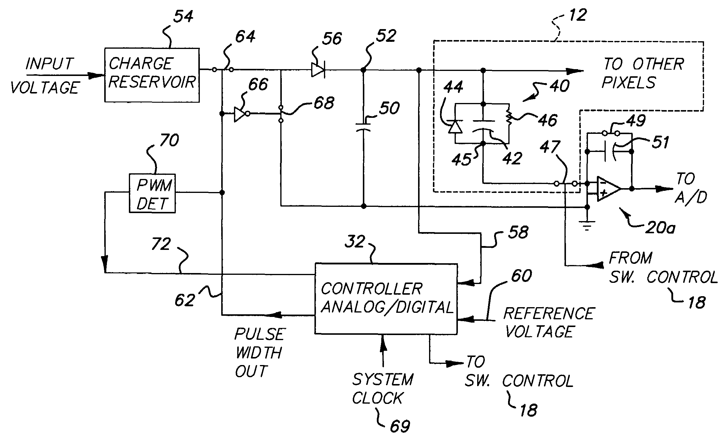
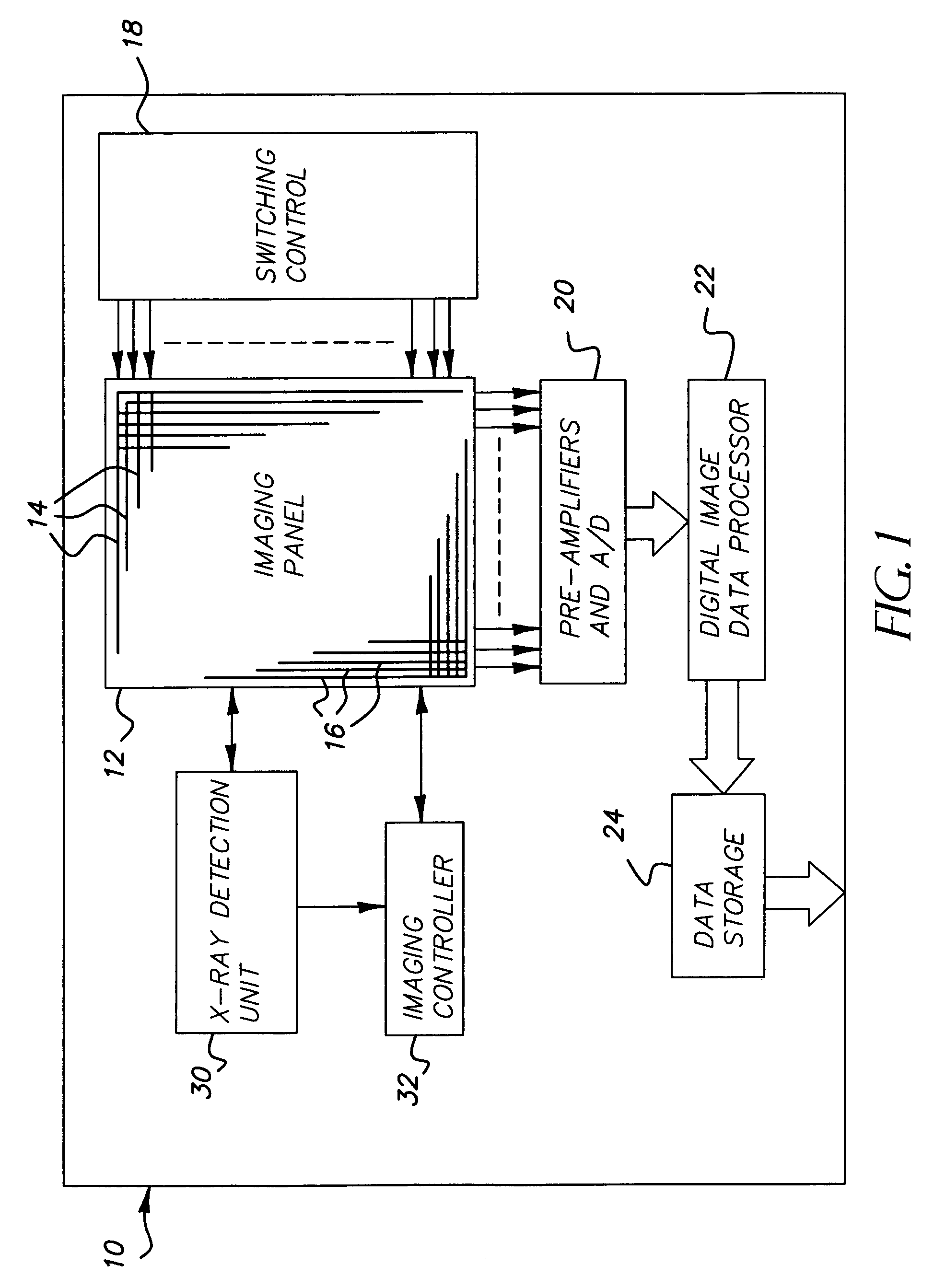
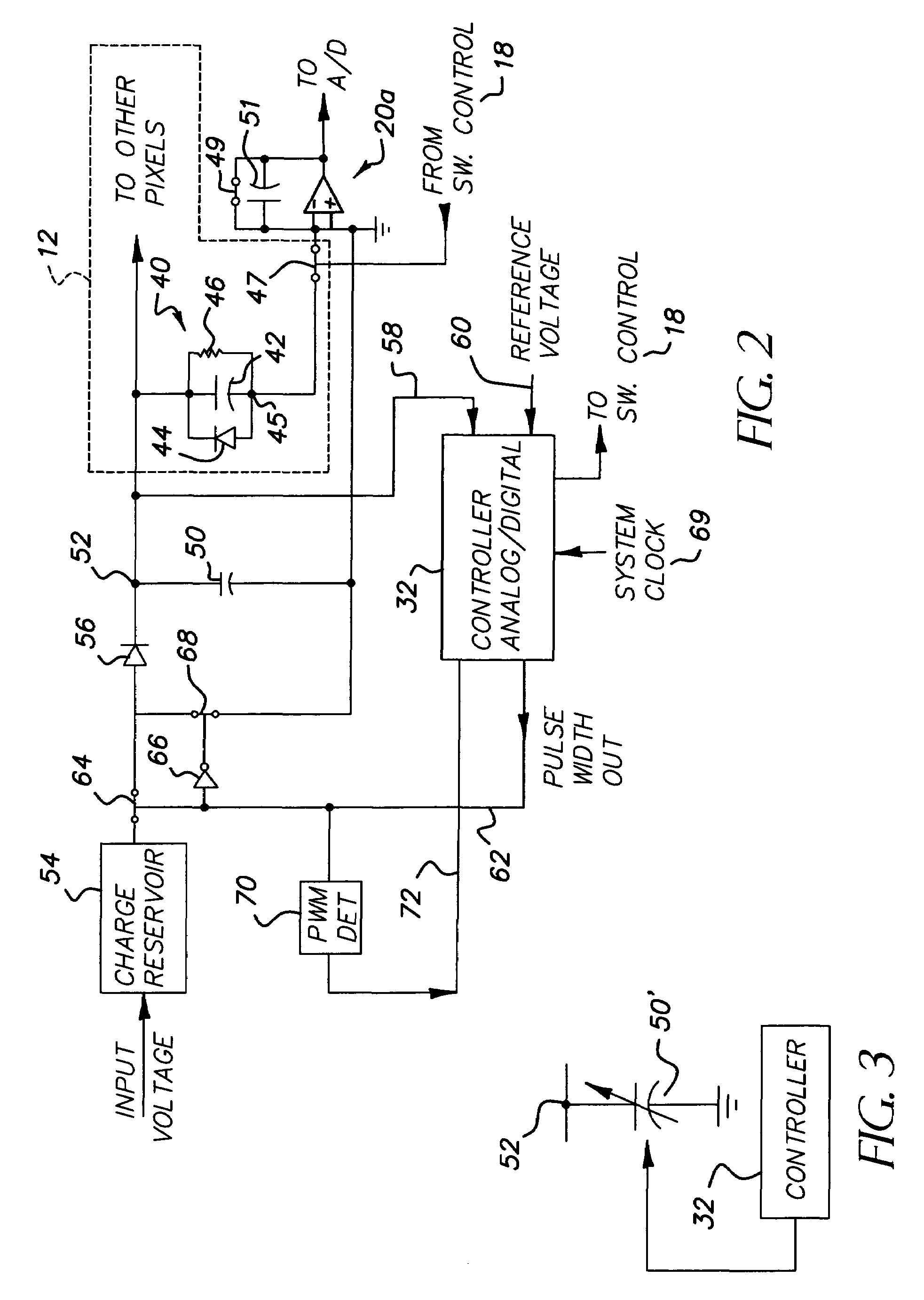
[0015]Referring to FIG. 1, an X-ray imaging sensor 10 comprises a flat panel X-ray imaging panel 12 in which discrete X-ray pixels are arranged in a two-dimensional array of rows and columns 14 and 16, respectively. As is well known in the art of digital radiography, the material in the pixels converts impinging X-rays into electrons which are initially stored in a charge element of the pixel for subsequent readout, typically done row-by-row under the control of a switching control unit 18. The charge of pixels in each column are conveyed in sequence, one row at a time, to charge amplifier (pre-amplifier) circuits, one for each column, in unit 20 and the charge values for each pixel are then converted by analog-to-digital (A / D) converters to digital data stored locally in RAM memory for subsequent transfer to a system digital image data processor 22 for suitable image processing operations prior to storage in a data storage unit 24.

[0016]In accordance with the invention, an X-ray de...


PUM


Abstract

A wireless, independent digital imaging sensor utilizes an external charge balance capacitor to establish a sense voltage at a common node between the charge capacitor and the pixel intrinsic capacitors in the sensor panel. A variable width pulse train responds to the sense voltage to control injection of charge to the external capacitor to maintain a constant voltage at the common equal to a reference voltage. An increase in pulse width above a threshold level representative of the onset of X-ray exposure is detected to generate an output control signal used to control subsequent image acquisition functions of the imaging sensor.

Description

FIELD OF THE INVENTION[0001]The general field of this invention is digital image radiography and, in particular, to digital radiography systems in which the digital imaging panel and accompanying electronics are in wireless communication with the main radiography system and may be used interchangeably with various manufacturer's X-ray systems.BACKGROUND OF THE INVENTION[0002]Digital radiography is achieving a growing acceptance as an alternative to photographic-based imaging technologies that rely on photographic film layers to capture radiation exposure to produce and store an image of a subject's internal physical features. With digital radiography, the radiation image exposures captured on radiation sensitive layers are converted, pixel by pixel, to electronic image data which is then stored in memory banks for subsequent read-out and display on suitable electronic image display devices. One of the driving forces in the success of digital radiography is the ability to rapidly vis...

Claims


Application Information

Patent Timeline
Patent Type & Authority Patents(United States)
IPC IPC(8): G01T1/24H05G1/60
CPCG01T1/24H04N5/32
Inventor DHURJATY, SREERAMGEISBUESCH, GORDONYORKSTON, JOHNSILBERMANN, JOSHUA M.HAWVER, JEFFERY R.
Owner CARESTREAM HEALTH INC
Why Eureka
Try Eureka