
Digital-control-type phase-composing circuit system

a phase-composing circuit and digital control technology, applied in the direction of electrical equipment, automatic control, etc., can solve the problems of difficult application of digital control-type phase-composing circuit systems, jitter in output clock signals, and easy impact on phase-composing circuits, so as to improve jitter resistance and expand lock range

Inactive Publication Date: 2007-05-01
MITSUBISHI ELECTRIC CORP
View PDF3 Cites 9 Cited by
  • Summary
  • Abstract
  • Description
  • Claims
  • Application Information

AI Technical Summary

Benefits of technology

The present invention provides a digital-control-type phase-composing circuit system that can improve jitter resistance and expand the lock range. The system includes a phase-composing circuit, a binary comparison circuit, two up / down counters, and a control signal. The system uses two input clock signals and a control signal to generate an output clock signal with a phase between the phases of the input clock signals. The system also uses a binary comparison circuit to compare the phase of the output clock signal with a reference clock signal and increments or decreases a count value based on the comparison. The most significant bit of the count value is outputted and used as a control signal. The system can improve jitter resistance and expand the lock range.

Problems solved by technology

Conversely, if the operating frequency of the counter is increased to expand the lock range, the phase-composing circuit is easily affected by high-frequency jitter when the reference clock signal and the output clock signal become in phase with each other.
If the reference clock signal has such jitter, the output clock signal from the phase comparison circuit is fluctuated by the jitter so that the value of the up / down counter in the following stage is changed unnecessarily frequently, thus causing jitter in the output clock signal.
For this reason, it is difficult to apply the conventional digital-control-type phase-composing circuit system particularly to a clock and data recovery (CDR) circuit which processes data containing a large amount of jitter.

Method used


Image

  • Digital-control-type phase-composing circuit system
  • Digital-control-type phase-composing circuit system
  • Digital-control-type phase-composing circuit system

Examples


Embodiment Construction

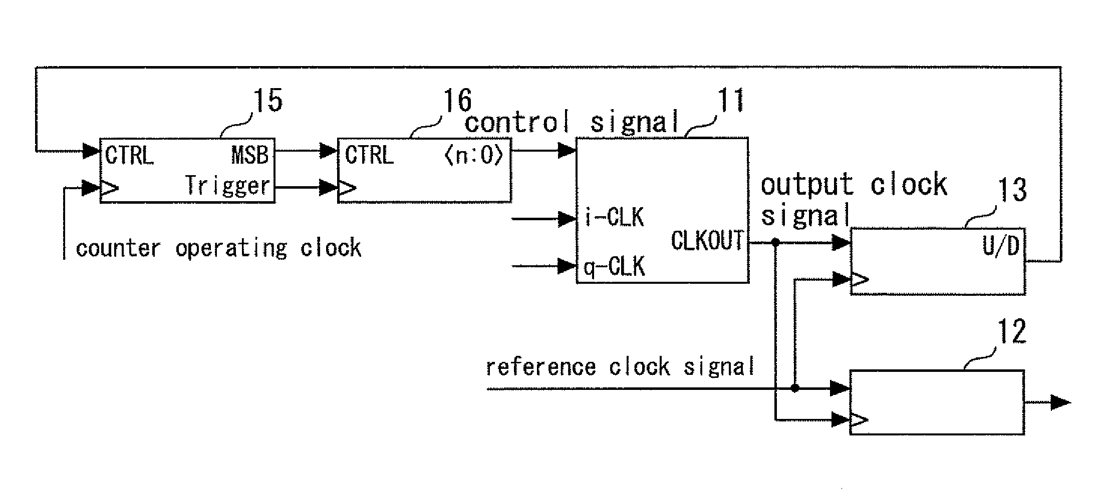
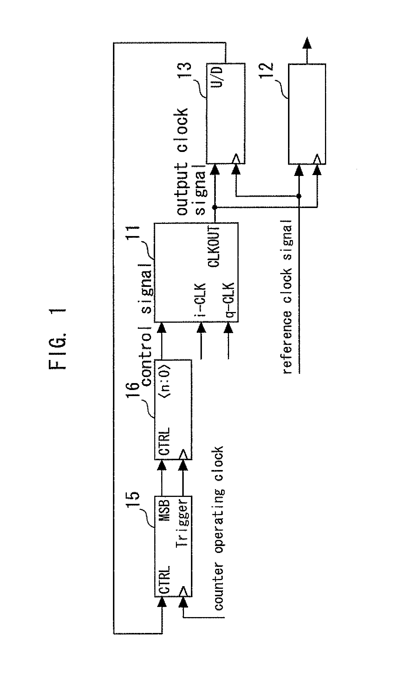
[0019]FIG. 1 is a block diagram showing a digital-control-type phase-composing circuit system according to an embodiment of the present invention. This system has a phase-composing circuit 11, a flip-flop circuit 12 and a binary phase comparison circuit 13, as does the conventional system. This system, however, has a first up / down counter 15 and a second up / down counter 16 in place of the up / down counter of the conventional system.

[0020]The phase-composing circuit 11 is supplied with two clock signals i-CLK and q-CLK differing in phase from each other, and a control signal. An output clock signal having a phase between the phases of the two input clock signals is composed on the basis of weighting through this control signal. This output clock signal and a reference clock signal are input to the flip-flop circuit 12.

[0021]The binary phase comparison circuit 13 compares the phase of the output clock signal and the phase of the reference clock signal. The binary phase comparison circu...


PUM


Abstract

A digital-control phase-composing circuit system has a phase-composing circuit which is supplied with two input clock signals having a phase difference therebetween and a control signal, and which composes an output clock signal having a phase between the phases of the two input clock signals on the basis of weighting through the control signal, a binary comparison circuit which compares the phase of the output clock signal to the phase of a reference clock signal, a first up / down counter which increments or decrements a first count value on the basis of the result of comparison made by the binary phase comparison circuit, outputs the most significant bit of the first count value, and outputs a clock pulse when a carry or a borrow occurs in the first count value, and a second up / down counter which operates on the basis of the clock pulse as an operating clock, increments or decrements a second count value on the basis of the most significant bit of the first count value, and outputs the second count value as the control signal.

Description

BACKGROUND OF THE INVENTION [0001]1. Field of the Invention[0002]The present invention relates to a digital-control-type phase-composing circuit system in which two clock signals having a phase difference therebetween are weighted through a control signal to compose an output clock signal having a phase between those of the two clock signals. More particularly, the present invention relates to a digital-control-type phase-composing circuit system capable of improving jitter resistance and expanding the lock range.[0003]2. Background Art[0004]In a delay locked loop (DLL) circuit, a digital-control-type phase-composing circuit system which combines two clock signals having a phase difference therebetween by weighting the signals is used (see, for example, Japanese Patent Laid-Open No. 2001-217682 and U.S. Pat. No. 5,485,490).[0005]FIG. 4 is a block diagram showing a conventional digital-control-type phase-composing circuit system. A phase-composing circuit 11 composes an output clock ...

Claims


Application Information

Patent Timeline
Patent Type & Authority Patents(United States)
IPC IPC(8): H03L7/00
CPCH03L7/0814H03L7/091H03L7/093
Inventor OKA, TOSHIHIDE
Owner MITSUBISHI ELECTRIC CORP
Learn More