Electrical machine

a technology of electric machines and motors, applied in the field of electric machines, can solve the problems of frequent vibration fatigue, and achieve the effect of reducing the proximity

Inactive Publication Date: 2007-05-08
SIEMENS AG
View PDF15 Cites 13 Cited by
  • Summary
  • Abstract
  • Description
  • Claims
  • Application Information

AI Technical Summary

Benefits of technology

[0008]Advantageously, the proximity effect can be reduced by implementing the electric conductors as flexible conductors, with a plurality of elements, which include individual bare wires that can be stranded or bunched. The cross-section of the stranded wire as well as of its filaments can have any imaginable geometric shapes, such as quadrilateral, rectangular, square, triangular or round.

Problems solved by technology

Disadvantageously, the cage rods have to be connected with the cage rings in a separate manufacturing step.
In addition, vibration fatigue frequently occurs due to the relatively rigid construction of the squirrel-cage, in particular at the solder joints.

Method used


Image

  • Electrical machine
  • Electrical machine
  • Electrical machine

Examples


Embodiment Construction

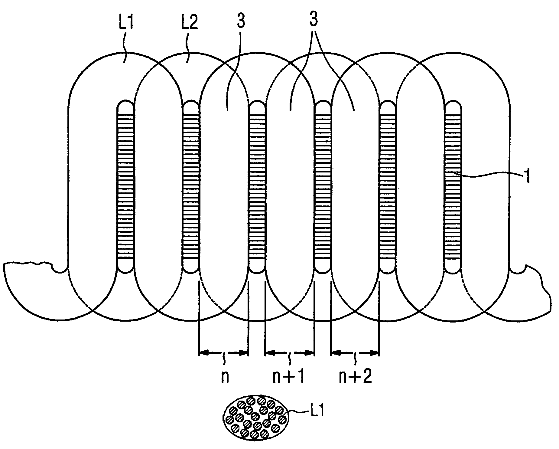
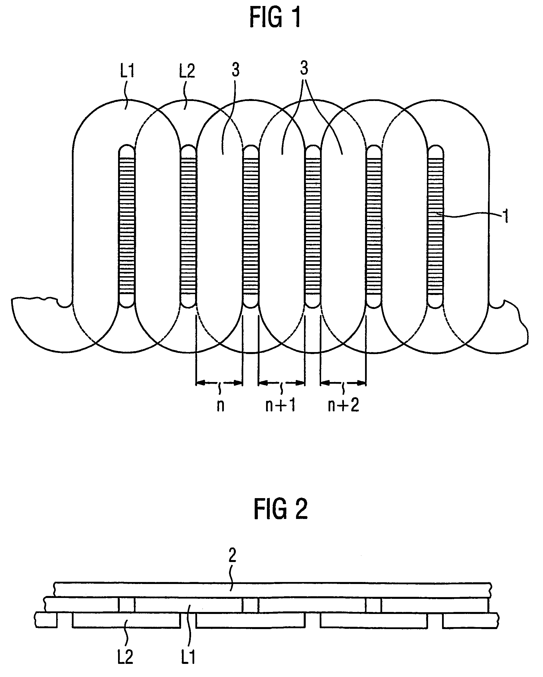
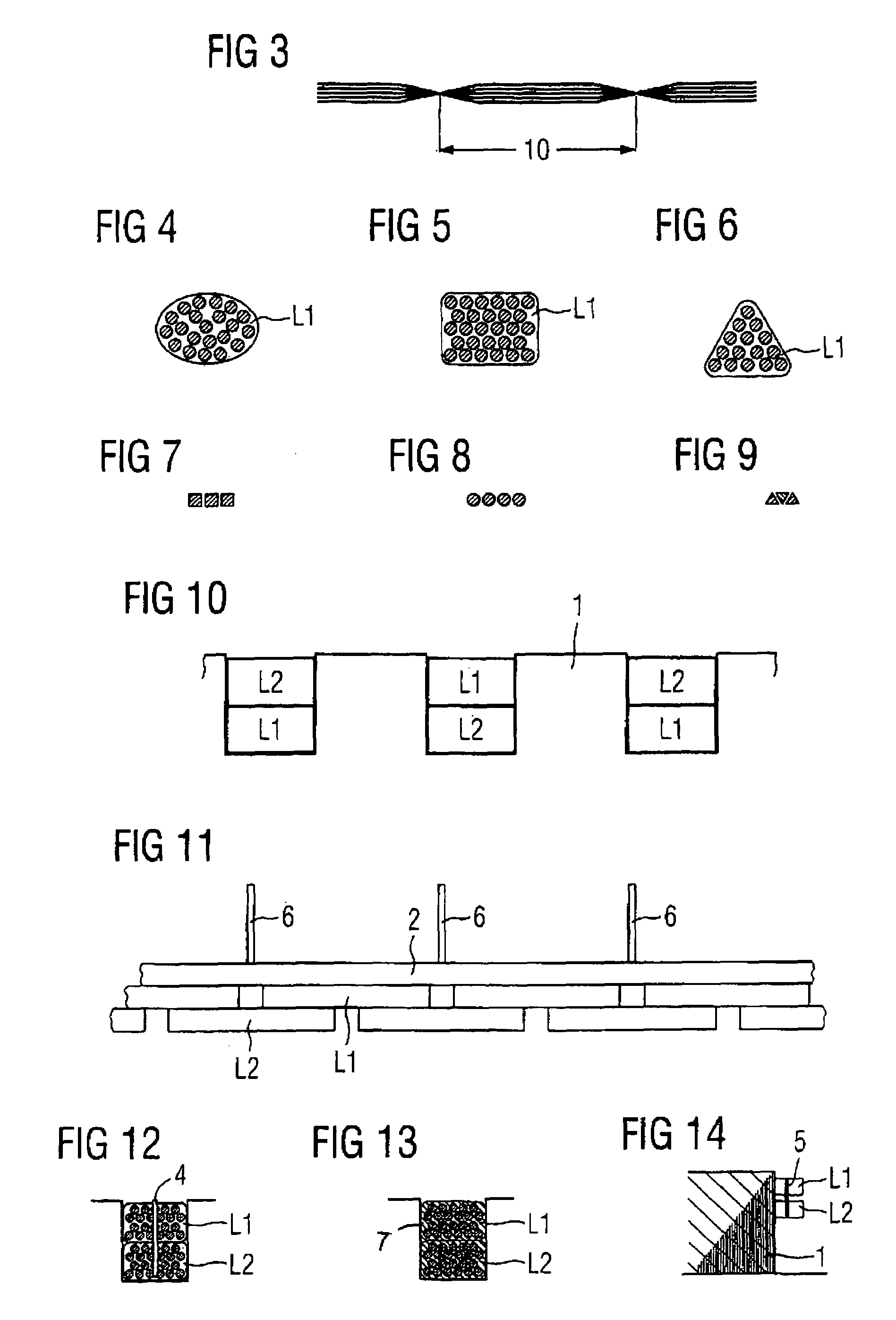
[0020]FIG. 1 shows, in an unrolled view, a squirrel-cage rotor with a lamination stack 1 that includes several exemplary slots n, n+1, n+2, which are machined out of the lamination stack 1. A conductor L2 is located in a lower layer of these slots and is wound in the opposite direction relative to a conductor L1 in an upper layer through the slots in a meander pattern. The conductors L1 and L2 are preferably stranded conductors consisting of individuals filaments. The stranded conductors are twisted with a predeterminable pitch 10, as shown by way of in FIG. 3.

[0021]The conductors L1 and L2 are electrically contacted preferably by pressing on the preferably bare stranded conductors in the slots n, n+1, n+2. The slot walls hereby provide the required back pressure. However, other types of electric contacts are possible, for example, by a conducting potting compound 7, as shown in FIG. 13. which can be filled into the slots or into certain predeterminable axial slot regions, for examp...


PUM


Abstract

In order to prevent, among other things, fatigue failures in squirrel-cage rotors of electrical machines, the invention provides that the squirrel-cage winding is comprised of flexible conductors.

Description

BACKGROUND OF THE INVENTION[0001]The invention relates to an electric machine with a squirrel-cage rotor.[0002]Asynchronous machines typically have rotors in form of a cage winding, whereby a respective rod is inserted in each of the slots, with the rods being connected at their respective end faces on the rotor by cage rings. Rods and cage rings are fabricated from aluminum or aluminum alloys by die casting, and have a higher resistance. However, copper, bronze or brass can also be used as electric conductors. The solid rods of the cage winding are typically inserted in the rotor without insulation and joined with the cage rings by soldering.[0003]Disadvantageously, the cage rods have to be connected with the cage rings in a separate manufacturing step. Moreover, the projection of the rods at the end faces of the rotor does not contribute to torque generation. In addition, vibration fatigue frequently occurs due to the relatively rigid construction of the squirrel-cage, in particul...

Claims


Application Information

Patent Timeline
Patent Type & Authority Patents(United States)
IPC IPC(8): H02K17/16
CPCH02K17/165
Inventor DRESSEL, GERHARD
Owner SIEMENS AG
Why Eureka
Try Eureka