Simulated visual glideslope indicator on aircraft display

a technology of aircraft display and simulated glideslope, which is applied in the direction of navigation instruments, instruments, teaching apparatus, etc., can solve the problems of not all runways have a radio glideslope, approach safety is thereby degraded, and the plane cannot provide a simulated glideslope or visual glide path angle, so as to increase the degree of coincidence

Active Publication Date: 2007-05-08
HONEYWELL INT INC
View PDF12 Cites 68 Cited by
  • Summary
  • Abstract
  • Description
  • Claims
  • Application Information

AI Technical Summary

Benefits of technology

[0020]According to various other aspects of the generator of the invention, the indicators further include illuminated indicators positioned on a cockpit display, such as a Primary Flight Display (PFD) or a Head-Up Display, and the illuminated indicators are presented conformally, i.e., positioned on the display to appear in positions consistent with ground-based airport lighting aids as seen on approach. Furthermore, the indicators may further include a pointer indicator programmed to provide information as to an amount of change in altitude to increase the degree of coincidence with the glide path. The pointer indicator may be presented so as to simulate a traditional vertical deviation scale.
[0021]According to still other aspects of the invention, the invention provides a computer program product for indicating deviation from a glide path, wherein the computer program product includes a computer-readable storage medium; and computer-readable program code means embodied in the medium, the computer-readable program code means having: a first computer-readable program code means for determining a global position from a received plurality of navigation d

Problems solved by technology

However, not all airport runways have an ILS generated radio glideslope.
While airport lighting aids such as PAPI or VASI or another lighting aid are located at most airports, not all airports provide either an ILS radio glideslope or a visual glide path angle; approach safet

Method used


Image

  • Simulated visual glideslope indicator on aircraft display
  • Simulated visual glideslope indicator on aircraft display
  • Simulated visual glideslope indicator on aircraft display

Examples


Embodiment Construction

[0036]In the Figures, like numerals indicate like elements.

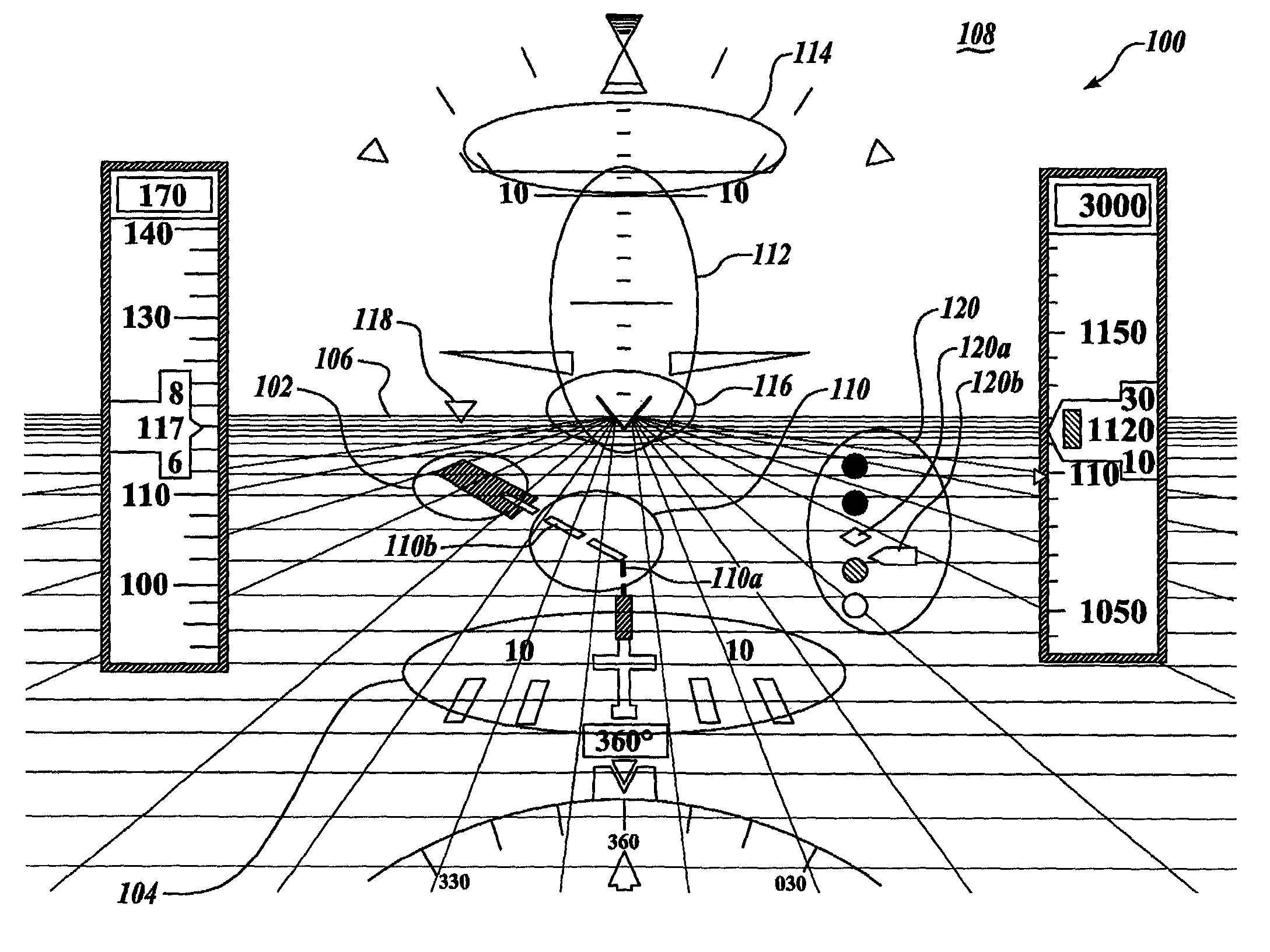
[0037]The present invention is an apparatus and method for generating and displaying a simulated visual glide path indicator. The apparatus includes a memory having stored therein a database of airport information, including runway location, elevation and direction information, accessible as a function of position; a processor coupled to receive position and elevation data and coupled to the memory for retrieving the airport information as a function of the position, the processor being structured to operate a computer program for generating a glide path, comparing the position and elevation data to the glide path, and generating a signal representative of deviation of the combined position and elevation data from the glide path; and a cockpit display being coupled to receive the deviation signal and being structured to illuminate a pattern of indicators as a function of the deviation signal. According to different embodimen...


PUM


Abstract

An apparatus and method for simulating airport lighting aids by providing a generator having a processor structured to receive a plurality of navigation signals representative of position and altitude of a host aircraft; a signal generator operated by the processor, the generator being structured to retrieve airport information from a database as a function of the position signal, compare the position and altitude signals with a glide path, and output a signal representative of a degree of coincidence with the glide path as a function of the position and altitude signals; and a plurality of indicators structured to receive the signal output by the signal generator and responsively output a visual indication of the degree of coincidence with the glide path.

Description

[0001]This application claims the benefit of U.S. Provisional Application Ser. No. 60 / 262,912, filed in the name of Charles L. Hett on Jan. 19, 2001, the complete disclosure of which is incorporated herein by reference.FIELD OF THE INVENTION[0002]The present invention relates to devices and methods for simulation of airport visual approach slope indicator, and in particular to a simulated airport lighting aid as displayed on a cockpit display.BACKGROUND OF THE INVENTION[0003]Aircraft landing at airports during marginal Visual Meteorological Conditions (VMC) or in cases of reduced cues such as night flight are aided by an Instrument Landing System (ILS). The ILS is a radio beam that originates on the ground at an ILS equipped airport and generates a glide slope that an aircraft can safely follow during an instrument approach to the runway. The ILS radio beam is detected by equipment onboard the aircraft and provides lateral, along-course, and vertical guidance to aircraft attempting ...

Claims


Application Information

Patent Timeline
IPC IPC(8): G06G7/72G01C23/00G08G5/02
CPCG01C23/005G08G5/0021G08G5/025
Inventor HETT, CHARLES L.
Owner HONEYWELL INT INC
Why Eureka
Try Eureka