
Heavy-duty demolition apparatus with blade stabilizing puck

a technology of heavy-duty demolition and stabilizing puck, which is applied in the direction of manufacturing tools, portable power-driven tools, building repairs, etc., can solve the problems of reducing and causing the blades of the scissors to crack or otherwise experience structural failure. , to achieve the effect of reducing the lateral stress on the upper jaw and improving the cutting ability of the tool

Active Publication Date: 2007-05-15
GENESIS ATTACHMENTS
View PDF70 Cites 48 Cited by
  • Summary
  • Abstract
  • Description
  • Claims
  • Application Information

AI Technical Summary

Benefits of technology

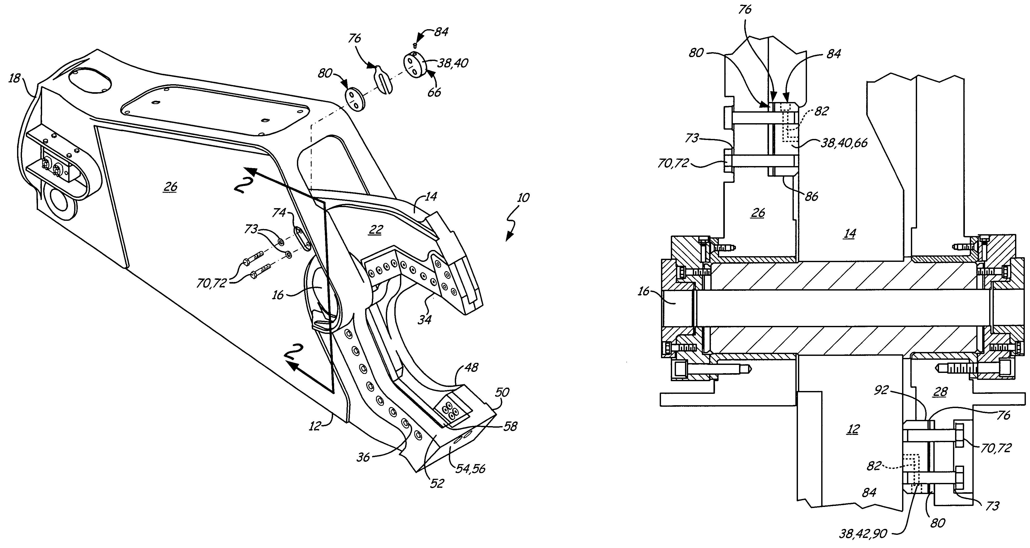
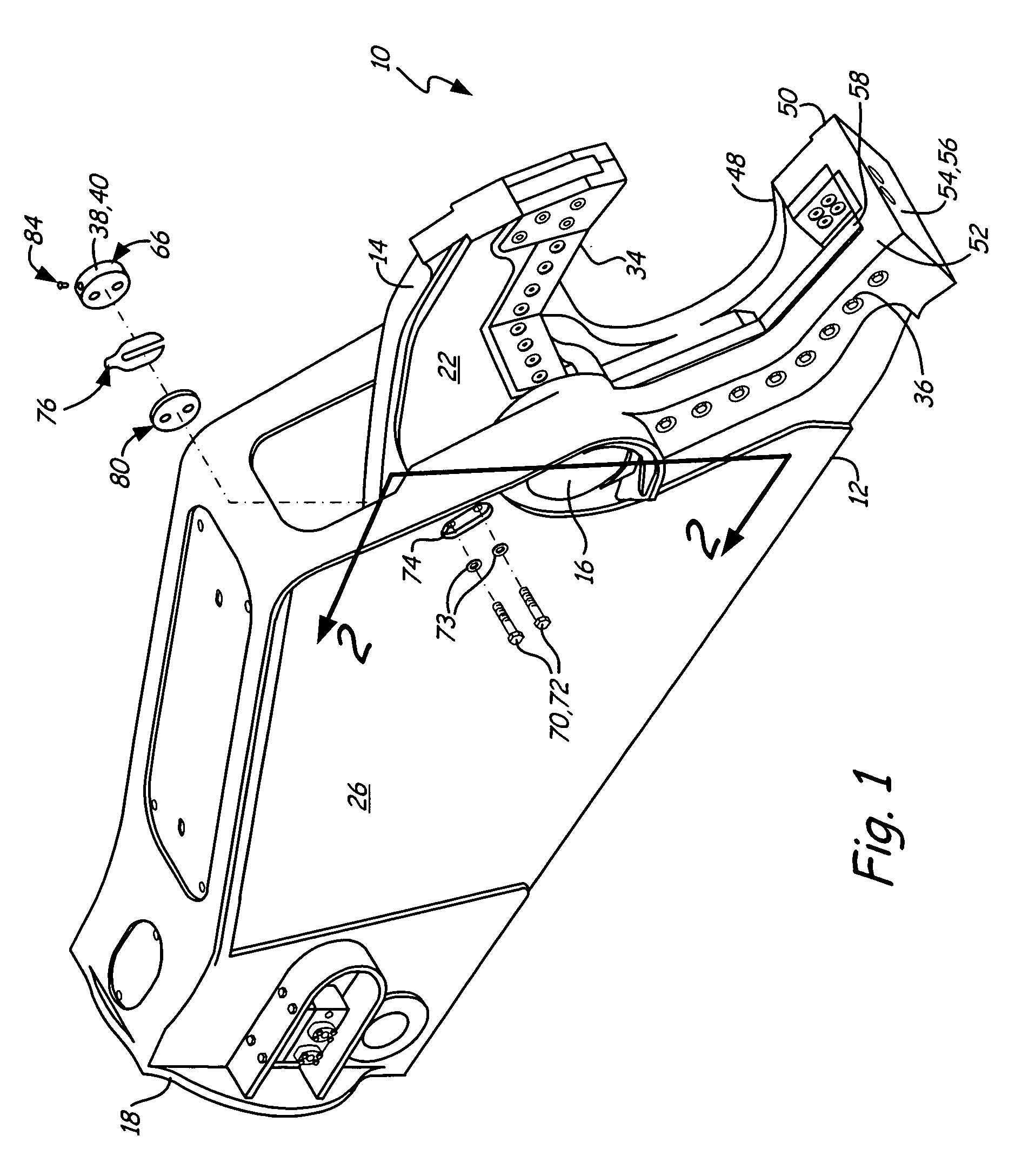
[0013]An object and advantage of the invention is to provide an improved heavy-duty material handling demolition tool for shearing and crushing scrap material with a blade stabilizing device which prevents the upper jaw from moving laterally relative to the lower jaw, thus improving the cutting ability of the tool for heavy scrap material.
[0014]Another object and advantage of the present invention is to provide a blade stabilizing device for a heavy-duty demolition tool which reduces lateral stress on the upper jaw caused due to shearing the workpiece.
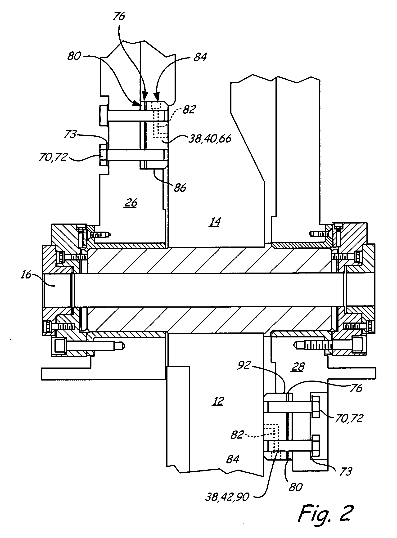
[0015]Another object and advantage of the present invention is that the blade stabilizing device is removable and replaceable when worn due to friction with the upper jaw.
[0016]Another object and advantage of the present invention is that the clearance between the blade stabilizing device and the upper jaw is adjustable to compensate for wear.
[0017]Another object and advantage of the present invention is that the blade stabilizing device contacts a wear surface on the upper jaw and the wear surface is dimensioned such that the blade stabilizing device does not contact the wear surface once the upper jaw is securely received in the lower jaw.
[0018]Another object and advantage of the present invention is that the blade stabilizing device may comprise a first stabilizer or puck mounted to the rear of the pivot point and a second stabilizer or puck mounted in front of the pivot point, thereby providing cross-bracing to the upper jaw.

Problems solved by technology

Unfortunately, great lateral as well as vertical pressure develops against the movable upper jaw as it contacts and proceeds to cut the workpiece.
This lateral pressure can cause the upper jaw to crack or otherwise experience structural failure.
The scissors' blades are forced laterally apart and may break.
In rebuilding highways for motor vehicle travel, and in the demolition of structures which are largely made of or incorporate reinforced concrete as structural members, the disposal of large pieces of concrete paving or reinforced concrete structure becomes a significant problem.
Many governmental regulations and practical considerations relating to the operation of landfills prohibit the disposal of concrete slabs and large reinforced concrete structures by simply burying them in the landfills.
It has been possible in the past to reduce concrete into particles and chunks by use of heavy duty shears, but such shears which are primarily designed for shearing steel and other metallic and wood structures have sharpened blades and are rather expensive for the purpose of reducing concrete slabs and structures which is thought to be accomplished in other ways.
Furthermore, crushing concrete may result in the development of lateral pressure against the movable upper jaw of a demolition shear in the same way that shearing metal does.

Method used


Image

  • Heavy-duty demolition apparatus with blade stabilizing puck
  • Heavy-duty demolition apparatus with blade stabilizing puck
  • Heavy-duty demolition apparatus with blade stabilizing puck

Examples


Embodiment Construction

[0026]The heavy-duty demolition apparatus of the present invention is generally referred to in the Figures as reference numeral 10.

[0027]Referring to FIGS. 1 through 6, the heavy-duty demolition apparatus 10 comprises a lower jaw 12, an upper jaw 14, pivot means 16 interconnecting the lower jaw 12 and upper jaw 14, and means 18 for attachment to the excavator (not shown). The means 18 may further include a rotator unit 20 allowing rotation of the demolition unit 10 about a longitudinal axis. The apparatus 10 also includes means 30 for attachment to the hydraulic system of an excavator (not shown) for closing and opening the upper jaw relative to the lower jaw. More specifically, the means 30 includes a cylinder 30a having a reciprocating piston 30b within the cylinder 30a. The cylinder 30a is connected to the hydraulic system of the excavator (not shown). The piston 30b connects to the upper jaw 14 at a knuckle 32.

[0028]The upper jaw 14 has a first side 22, and a second side 24. The...


PUM

PropertyMeasurementUnit
sizesaaaaaaaaaa
sizesaaaaaaaaaa
sizesaaaaaaaaaa

Abstract

A blade stabilizer device for a heavy-duty material handling demolition tool for shearing and crushing scrap material which includes a lower jaw connected to the boom structure of a hydraulic system of an excavator has an upper jaw pivotally connected to and closable upon the lower jaw at a pivot point. The blade stabilizing device consists of a wear guide pad supported by the lower jaw adjacent the pivot point slidably engaging the movable upper jaw to keep the upper jaw in close engagement with the lower jaw. The wear guide pad is mounted behind the pivot point. A second wear guide pad may be mounted in front of the pivot point on the opposite side of the upper jaw to cross-brace the upper jaw.

Description

BACKGROUND OF THE INVENTION[0001]A fuller understanding of the operation of the demolition apparatus of the present invention may be achieved by studying U.S. Pat. Nos. 4,519,135 and 6,061,911, hereby incorporated by reference. This invention relates to a heavy duty demolition apparatus, especially adapted to be mounted on a rigid boom of a mobile vehicle and particularly adapted to be mounted on the dipper stick of an excavator, with a blade stabilizing device or puck to keep the upper jaw of the apparatus from moving laterally relative to the lower jaw and breaking during the shearing operation on a workpiece.[0002]Heavy duty shears of the type that are powered by hydraulic cylinders are proving more and more useful in handling scrap and especially metal scrap of all sorts. Such scrap comes in many different forms, and may be in the form of pipes made of steel or soft iron or cast iron, ranging in sizes from 2 inches or smaller, and up to 8 or 10 inches in diameter or larger; stru...

Claims


Application Information

Patent Timeline
Patent Type & Authority Patents(United States)
IPC IPC(8): B26D5/08B02C1/02B23D31/00B25F3/00B26B1/00E02F3/96
CPCB23D31/008E02F3/965E04G23/082Y10T83/8815Y10T83/9447
Inventor ALSETH, TIMOTHY L.BACON, BRUCE E.CHRISTENSON, ROSS D.
Owner GENESIS ATTACHMENTS
Learn More