Methods and apparatus for deicing airfoils or rotor blades

a technology applied in the field of wind turbines, can solve the problems of reduced lifting capacity, reduced aerodynamic rotor blade performance, and difficulty in servicing of airfoils or rotor blades

Inactive Publication Date: 2007-05-15
GENERAL ELECTRIC CO
View PDF11 Cites 98 Cited by
  • Summary
  • Abstract
  • Description
  • Claims
  • Application Information

AI Technical Summary

Benefits of technology

[0009]It will be appreciated that configurations of the present invention provide effective detection of ice on rotor blades and / or effective deicing of rotor blades.

Problems solved by technology

Ice buildup typically occurs on the leading edge of the airfoil and causes a reduced lifting capability.
For air turbines, this modification can result in diminished aerodynamic rotor blade performance.
(For airfoils on airplanes, a similar loss in performance can result in a crash.)
Airfoils or rotor blades can be difficult to service due to their operating environment.
However, inflation of the air bladder alters the aerodynamics of the airfoil or rotor blade, and the air bladder itself may be or become subject to fatigue and failure in at least some environments.

Method used


Image

  • Methods and apparatus for deicing airfoils or rotor blades
  • Methods and apparatus for deicing airfoils or rotor blades
  • Methods and apparatus for deicing airfoils or rotor blades

Examples


Embodiment Construction

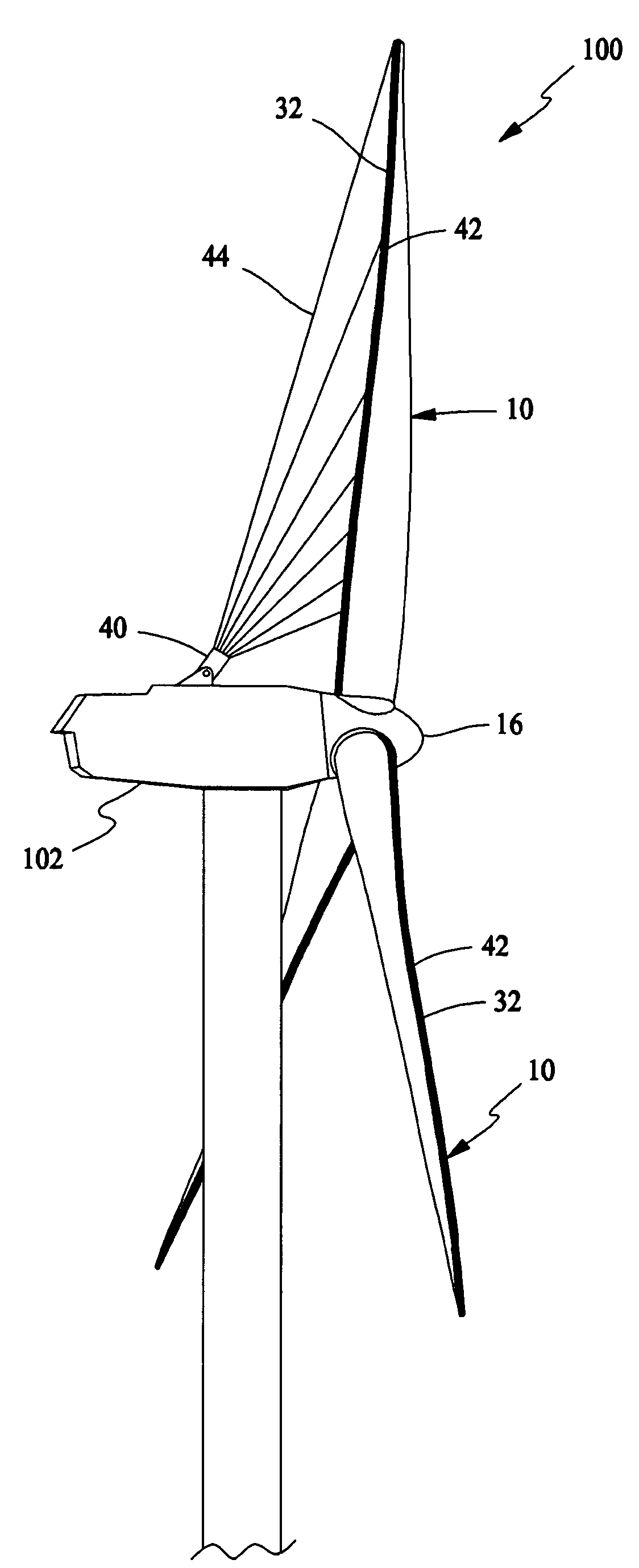
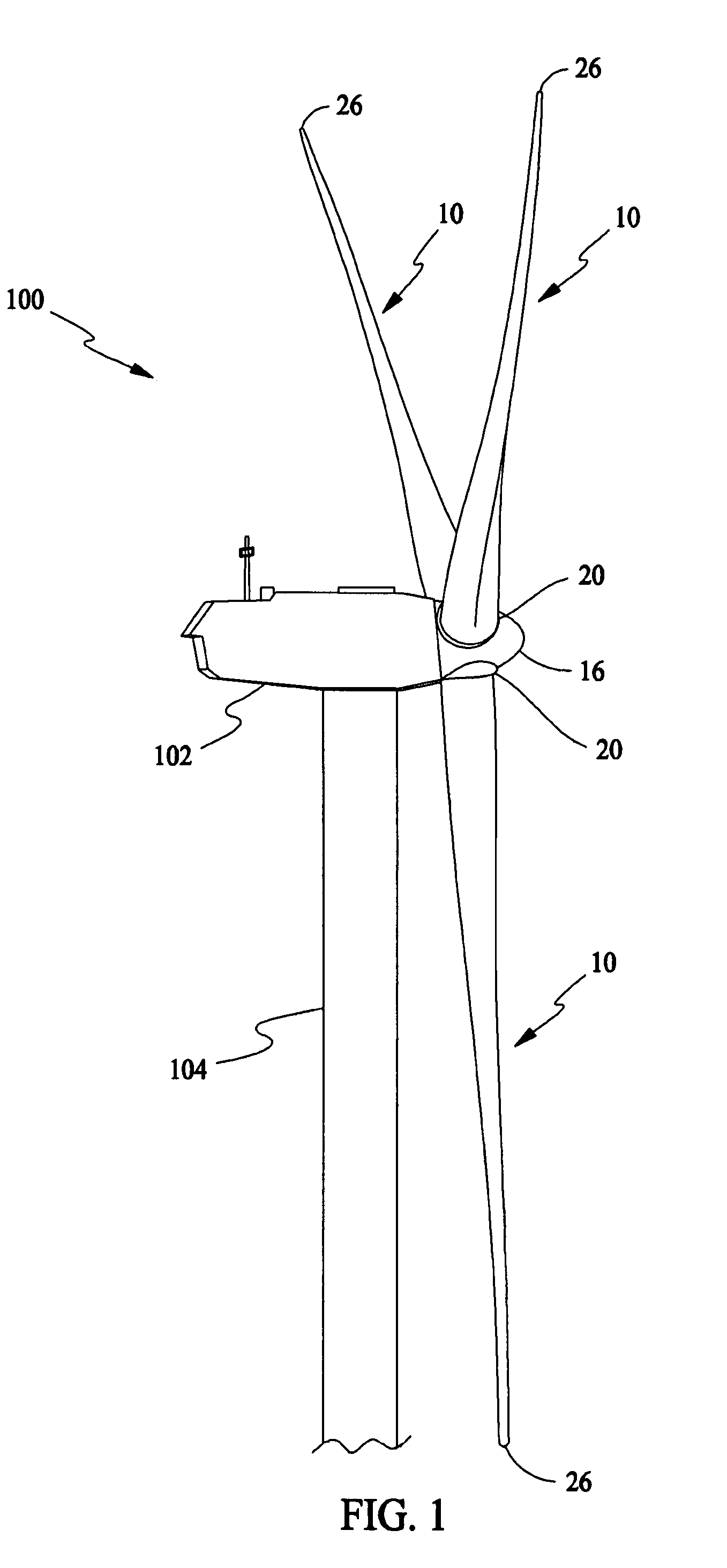
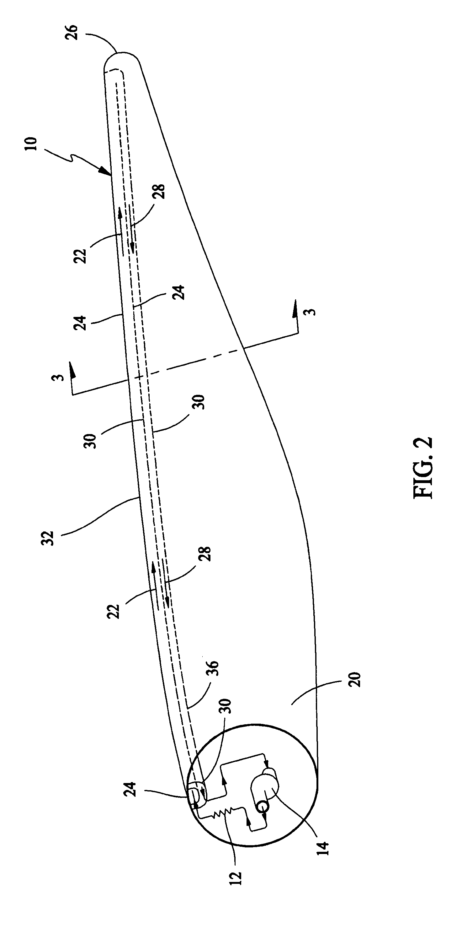
[0015]In some configurations and referring to FIGS. 1, 2, and 4, the present invention employs blade heating to deice airfoils or rotor blade(s) 10 of a wind turbine 100. Nacelle 102 of wind turbine 100 may be mounted on a tall tower 104, only a portion of which is shown in FIG. 1. A resistive heating unit 12 coupled with a blower 14 is mounted in a hub 16 of a wind turbine 100 or near a blade root 20. Heated air 22 is directed through a outflow channel 24 from blade root 20 towards blade tip 26 and then recirculated 28 via a return channel 30 from blade tip 26 to blade root 20, whereupon heating unit 12 reheats the return air 28. In this manner, warm return air 28 insulates outgoing hot air 22 and heat is dissipated primarily into the leading edge 32 of rotor blade 10. In some configurations and referring to FIG. 3, Insulation 34 can be added to an outside wall 36 of return channel 30 to optimize heat transfer to leading edge 32. Electrical power is provided to resistive heating un...


PUM


Abstract

A method for deicing a rotor blade having a blade root, a blade tip, and a leading edge in which the rotor blade is operably coupled to a hub of a turbine includes circulating heated air through an outflow channel from the blade root towards the blade tip, recirculating the heated air via a return channel from the blade tip to the blade root, whereupon the recirculated heated air becomes returned air, and reheating the returned air for further circulation.

Description

BACKGROUND OF THE INVENTION[0001]This invention relates generally to wind turbines, and more specifically to methods and apparatus for increasing the efficiency of wind turbines.[0002]Recently, wind turbines have received increased attention as environmentally safe and relatively inexpensive alternative energy sources. With this growing interest, considerable efforts have been made to develop wind turbines that are reliable and efficient.[0003]Generally, a wind turbine includes a rotor having one or more blades. The rotor is mounted on a housing or nacelle, which is positioned on top of a truss or tubular tower. The turbine's blades transform wind energy into a rotational torque or force that drives one or more generators, rotationally coupled to the rotor through a gearbox. The gearbox steps up the inherently low rotational speed of the turbine rotor for the generator to efficiently convert mechanical energy to electrical energy, which is fed into a utility grid. Gearless direct dr...

Claims


Application Information

Patent Timeline
Patent Type & Authority Patents(United States)
IPC IPC(8): F03D9/00F03B13/00
CPCF01D11/00F01D25/02F03D11/0025F05B2270/8041Y02E10/721Y02E10/722Y02T50/671Y10S415/905F05D2270/8041F03D80/40Y02E10/72Y02T50/60
Inventor LEMIEUX, DAVID LAWRENCE
Owner GENERAL ELECTRIC CO
Why Eureka
Try Eureka