
Enhanced end effector arm arrangement for CMP pad conditioning

a technology of end effector arm and cmp pad, which is applied in the direction of grinding drive, grinding drive, abrasive surface conditioning device, etc., can solve the problems of limiting the potential for contamination of the cmp system and breakage, and achieves well-controlled and efficient movement and operation. , the effect of improving the end effector arm configuration

Inactive Publication Date: 2007-05-15
TBW IND INC
View PDF14 Cites 18 Cited by
  • Summary
  • Abstract
  • Description
  • Claims
  • Application Information

AI Technical Summary

Benefits of technology

"The present invention is about a conditioning apparatus for a chemical mechanical planarization (CMP) system. It addresses the need for an improved end effector arm configuration that provides well-controlled and efficient movement and operation of the effector arm with respect to the polishing pad surface during conditioning processes. The enhanced end effector arm has various features that simplify maintenance of the conditioning disk, improve precision of downforce applied by the conditioning disk, and ensure consistent dressing of the polishing pad surface. It also uses a quick release mechanism for replacing the abrasive conditioning disk without the need for additional tools or physical handling of the disk. The conditioning disk is automatically aligned with the conditioner head using magnetic locators, and a static friction-free actuator is used to control both the vertical movement of the end effector arm and the downforce applied by the arm's conditioner head on the CMP polishing pad. The invention also addresses the problem of tilting of the conditioner head as the polishing pad ages by using a dual-drive / intermediate pulley arrangement and a split dual-drive belt to minimize the unwanted tilting movement of the belt drive system."

Problems solved by technology

The elimination of these prior art actions is seen as thus limiting the potential for contamination of the CMP system, or for breakage to occur as maintenance operations are performed on the abrasive conditioning disk.

Method used


Image

  • Enhanced end effector arm arrangement for CMP pad conditioning
  • Enhanced end effector arm arrangement for CMP pad conditioning
  • Enhanced end effector arm arrangement for CMP pad conditioning

Examples


Embodiment Construction

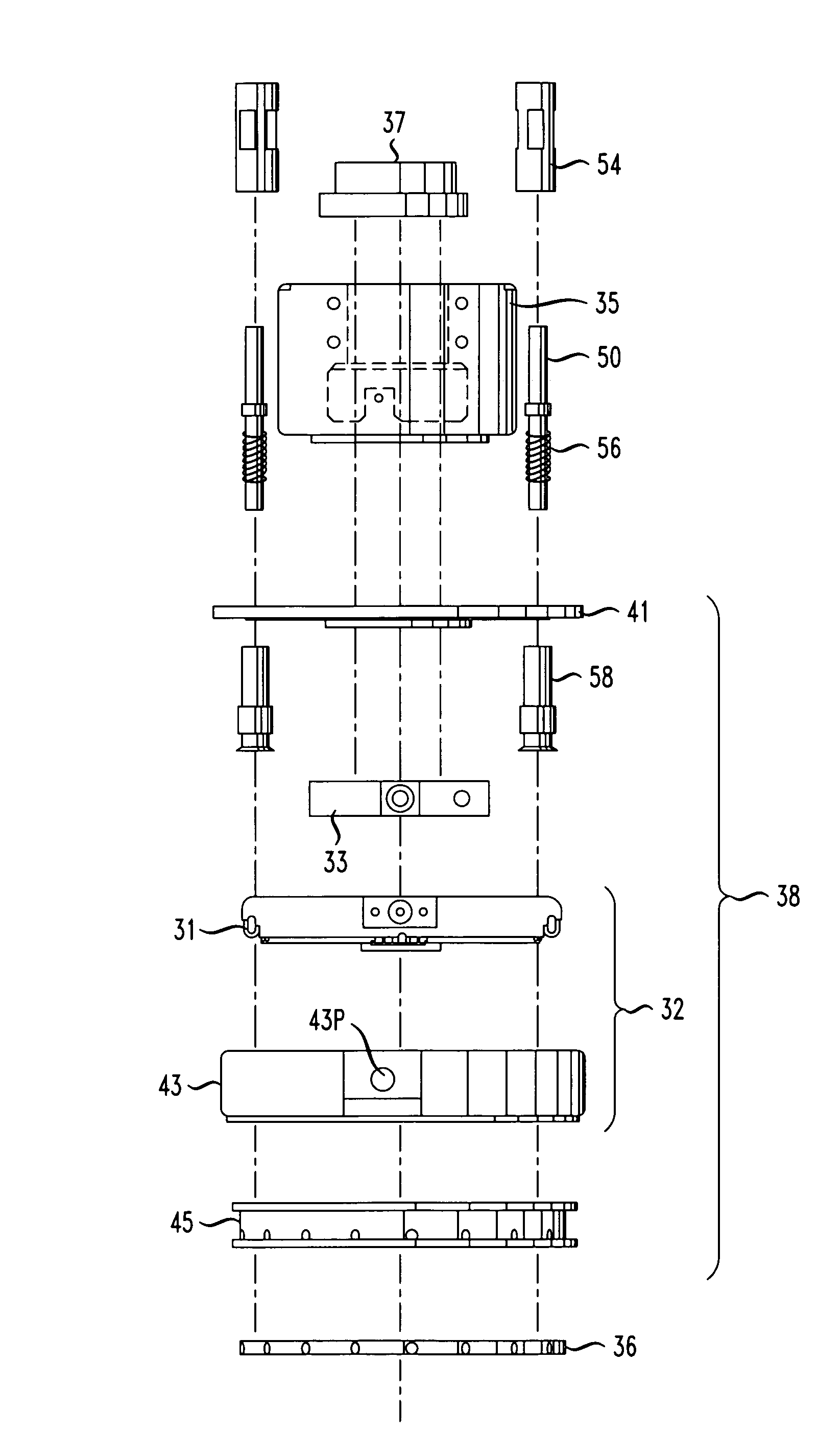
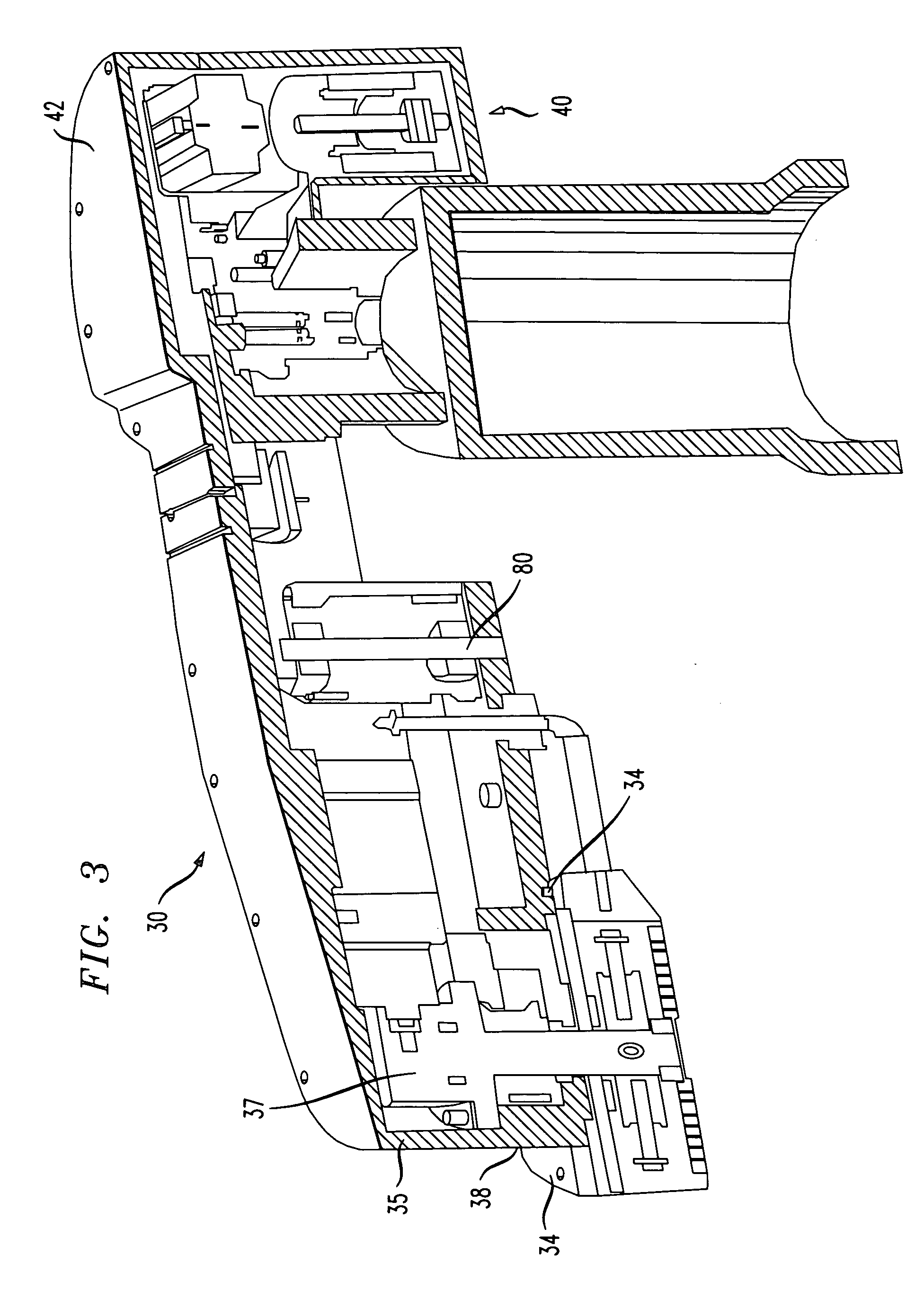
[0028]In accordance with the present invention, an enhanced end effector arm for CMP systems has been developed that provides for an accurate and well-controlled conditioning process, which thus results in improving the quality and longevity of the polishing pad itself and ultimately improves the quality of the polishing / planarization processes performed by the CMP system. Inasmuch as the end effector arm is essentially the control mechanism of the conditioning operation, improvements in the various aspects of the arm's components are quickly realized in terms of increased reliability and simplified maintenance of the CMP apparatus, as well as in terms of improving the quality of the overall conditioning and polishing processes. The enhanced end effector arm of the present invention incorporates various features that function in a cooperative and cumulative manner to improve the performance and reliability of the arm itself, resulting in also improving the overall quality of the con...


PUM

PropertyMeasurementUnit
weightaaaaaaaaaa
weightaaaaaaaaaa
forceaaaaaaaaaa

Abstract

A CMP conditioning apparatus enhanced end effector arm for improving the reliability of the apparatus and the quality of the conditioning and polishing operations includes a conditioner head with features that provide for simplified alignment / attachment of a conditioning disk to the arm, while also providing a “quick release” mechanism for maintenance operations. The enhanced arm also includes an improved actuator that provides for a static friction (“stiction”)-free movement of the arm and better control of the downforce applied by the conditioning disk to the polishing pad. A dual-drive pulley system is used within the enhanced end effector arm to minimize the tilting of the drive belts within the effector arm as the arm pivots to follow the contour of an “aging” polishing pad.

Description

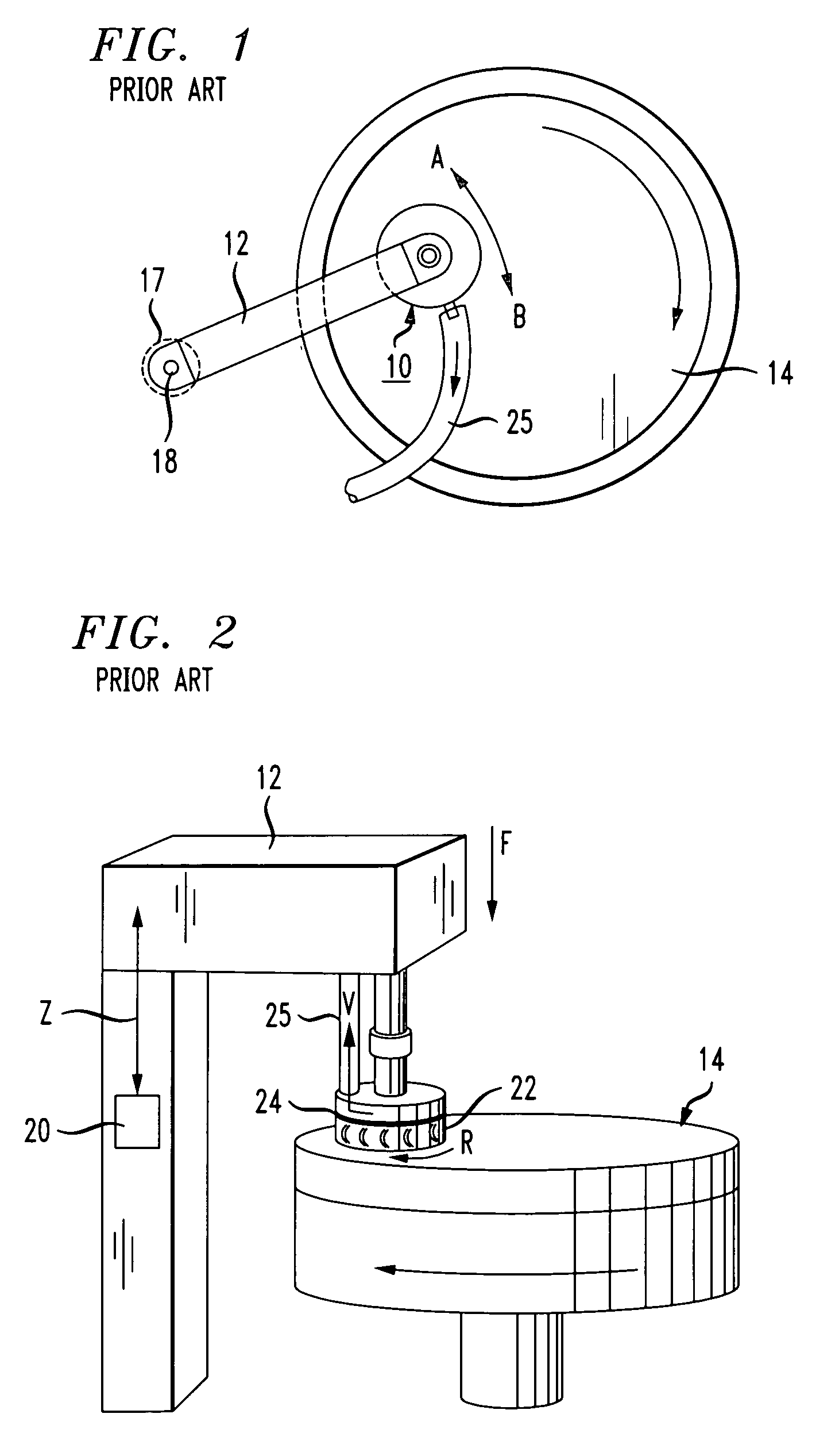
CROSS-REFERENCE TO RELATED APPLICATION[0001]This application claims the benefit of U.S. Provisional Application No. 60 / 697,893, filed Jul. 9, 2005.TECHNICAL FIELD[0002]The present invention relates to conditioning apparatus for use in a chemical mechanical planarization (CMP) system and, more particularly, to an improved end effector arm configuration to provide well-controlled, reliable and efficient movement and operation of the end effector arm with respect to the polishing pad surface.BACKGROUND OF THE INVENTION[0003]In the field of chemical mechanical planarization (CMP), a process known as “pad conditioning” or “pad dressing” is used to restore the surface of the polishing pad and remove surface glazing by dislodging particulates and spent polishing slurry from the pad. Pad conditioning also re-planarizes the polishing pad by selectively removing pad material so as to roughen the newly-exposed pad surface. Pad conditioning may be performed “ex-situ” (i.e., conditioning the pol...

Claims


Application Information

Patent Timeline
Patent Type & Authority Patents(United States)
IPC IPC(8): B24B33/00B24B53/017
CPCB24B53/017B24B51/00B24B53/12B24B29/00H01L21/304
Inventor BENNER, STEPHEN J.
Owner TBW IND INC
Learn More