Tunnel port apparatus with serial gas-check assembly

a tube apparatus and serial technology, applied in the field of catheter and tube apparatus surgical placement, can solve the problems of threatening the functionality of the catheter, flow obstruction, and hernia formation, and achieve the effects of reducing the risk of infection

Active Publication Date: 2007-05-15
CRABTREE JOHN H
View PDF35 Cites 7 Cited by
  • Summary
  • Abstract
  • Description
  • Claims
  • Application Information

AI Technical Summary

Benefits of technology

[0020]Insertion steps of the port cannula may be considered to have various elements. The physical shape of the resulting tissue tract and the physical force that is utilized by an operator to advance the port cannula through tissue are two of these elements. Conventional port devices establish simple, straight passages through abdominal walls, for example, and in this case the operator is primarily concerned with the force required to advance the port through tissues. This process becomes more complex when it is necessary to simultaneously control both the shape of the tissue tract being formed as well as the force that is used to create the tract. Control of one element is generally maintained at the expense of the other. However, the apparatus of the present invention and its associated method of use provides for the consideration of these as separate steps during cannula port placement, thereby providing greater control, safely and accuracy during the insertion process and formation of a tunnel through tissue. Utilizing the guideneedle assembly in the initial steps permits the operator to concentrate on the position, direction and length of the tissue tract (tunnel). The configuration of the guideneedle assembly provides for improved and relatively facile maneuverability with negligible force due to the small cross section of a hollow core needle (which minimizes force needed to advance through tissue) that is utilized in this initial insertion step. Once positioned through the tissue, the operator can concentrate on applying force required to advance the port cannula over the guideneedle assembly while maintaining the position first provided by the guideneedle.
[0021]In still other embodiments, tunnel port apparatus of the present invention is comprised of one or more apertured diaphragms that preserve pneumatic competence of a serial gas-check assembly. Distance between apertured diaphragms, can be designed to exceed the length of a surface irregularity of a component that is being advanced through the serial gas-check assembly, such that when a portion of the surface irregularity deforms a seal provided by any portion or component of the serial gas-check assembly, other serial gas-check assembly components are provided that will maintain pneumatic competence and check / stop the leakage / backflow of a fluid or gas, such as an insufflating gas. As the surface irregularity of the component passes through one of the apertured diaphragms, one or more apertured diaphragms proximal or distal to this point preserves competence of the serial gas-check assembly by maintaining a snug fit around another portion / portions of the component being advanced therethrough.

Problems solved by technology

After infectious complications, mechanical problems are the most common difficulties that threaten the functionality of the catheter.
Mechanical problems include flow obstruction from blockage of the catheter tip by omentum, displacement of the intraperitoneal catheter segment to a position of poor drainage function, pericannular leakage of dialysate fluid through the abdominal wall, and hernia formation produced by abdominal wall weakening at the catheter insertion site.
The consequences of mechanical complications include additional operative procedures to remedy the problem, replacement of the catheter, or loss of the option of peritoneal dialysis as renal replacement therapy with permanent transfer to hemodialysis.
The wide range of reported outcomes stems from a lack of uniformity in implantation tools and methodology.
Devices generally used to perform percutaneous insertion and muscular tunneling are borrowed laparoscopic port cannulas that are oversized, possess dangerous trocar blades, and often require considerable modification that departs from the manner of intended use.
The variety of available port devices leaves too much variability in application and thus reduces reproducibility and impedes establishing standard methodology for peritoneal dialysis catheter implantation.
Abdominal wall tunneling by open dissection is not practical due to the considerable disruption of tissues required to create a passage of sufficient length.
The identified problems with existing tools and methods include excessive tissue dissection that may result from open dissection, which increase the risk for pericannular leaks and hernias and limits the length of an abdominal wall tunnel.
Additionally, there is an increase in the risk of hemorrhage, leaks, and hernias associated with utilizing trocar-tipped laparoscopic ports with cutting blades and / or oversized laparoscopic ports.
Furthermore, laparoscopic ports utilizing an overlying plastic sleeve for radial expansion limit the length of the abdominal wall tunnel.
The unsupported plastic sleeve tends to kink in the tissue tract when a guideneedle is removed and prevents safe insertion of a port cannula.
Physical irregularities of components, or portions thereof, being advanced through the valve mechanism may defeat valve competence.
If the irregularity of a component surface exceeds the elastic capabilities of the apertured diaphragm to conform to that surface and maintain a seal, backflow of insulation gases will occur, leading to a collapse / deflation of a previously gas-expanded space, such as a peritoneal cavity, for instance.

Method used


Image

  • Tunnel port apparatus with serial gas-check assembly
  • Tunnel port apparatus with serial gas-check assembly
  • Tunnel port apparatus with serial gas-check assembly

Examples


Embodiment Construction

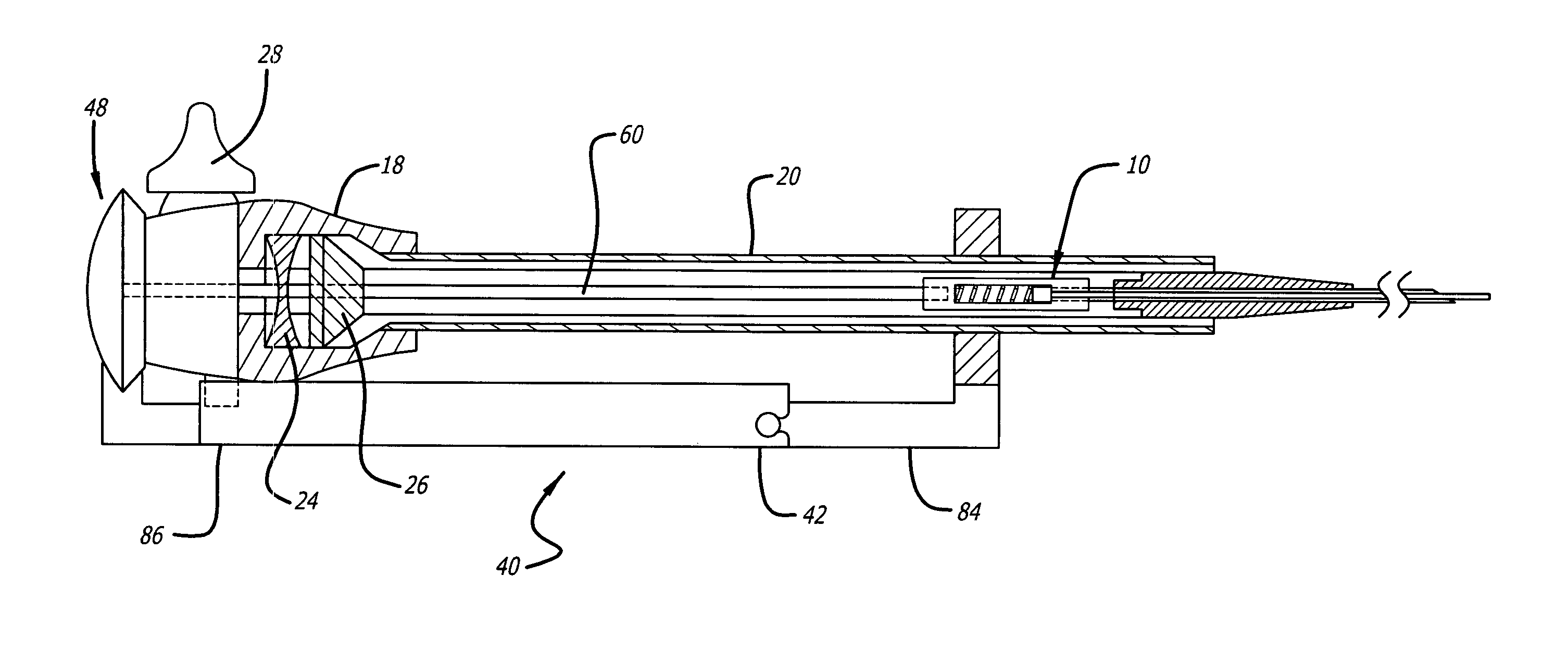
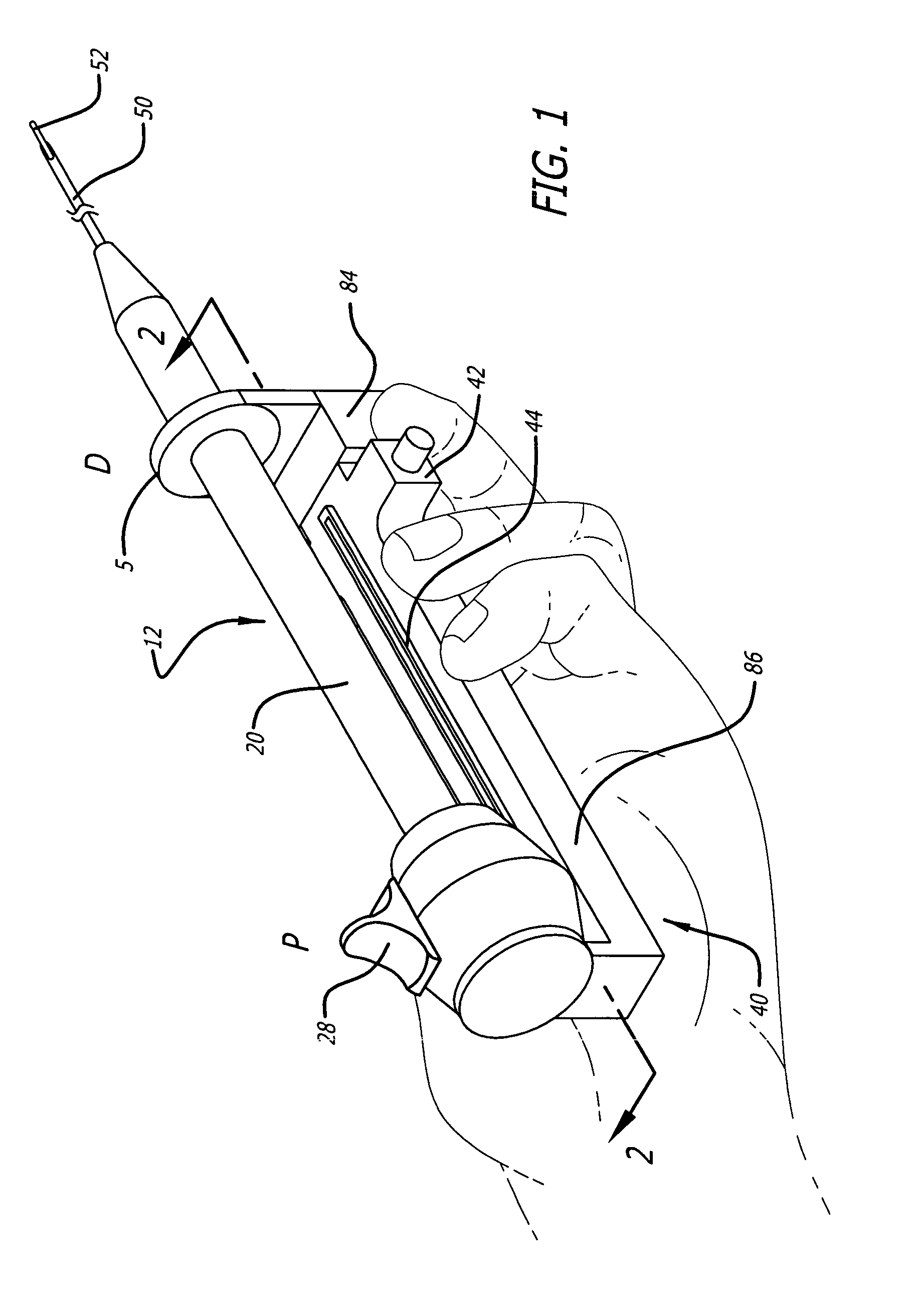
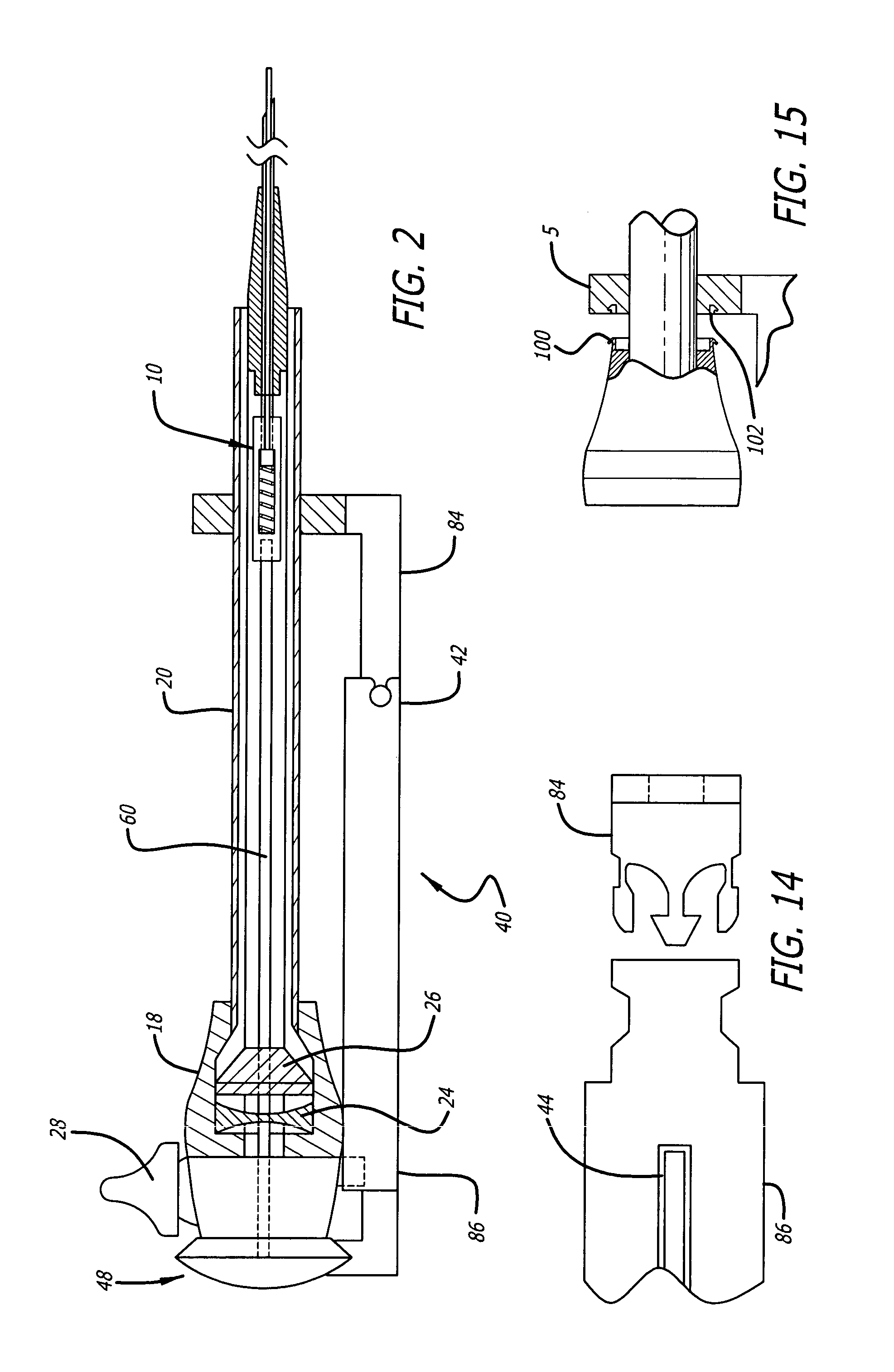
[0041]Now turning to FIG. 1, an exemplary tunnel port apparatus is depicted being held by an operator in an exemplary grip. Components of the apparatus comprise a guideneedle assembly 10 (not shown, see FIGS. 2 and 6) with overlying port cannula 12 in conjunction with a support frame 40. Support frame in this embodiment has a proximal frame portion 86 and a distal frame portion 84, which has an apertured portion 5 that supports the hollow tube 20 of port cannula 12. The guideneedle assembly 10 and port cannula 12 are designated to have a proximal end (P) that is oriented toward the operator of the apparatus and a distal end (D) that is oriented toward a subject, such as an animal, including humans.

[0042]The port cannula 12 comprises a proximal valve apparatus 18 and a distal hollow tube 20 (FIGS. 2 and 3). The valve apparatus 18 comprises a channel passage 17 inline with the axis of the lumen 21 of the distal hollow tube 20. The valve apparatus 18 comprises a perforated elastic memb...


PUM


Abstract

Provided herein is a port apparatus and method for inserting a tube device, in particular peritoneal dialysis catheters, into an organism. Access to the peritoneal cavity for dialysis is established by creating a controlled cutaneoperitoneal fistula with a catheter device that bridges the abdominal wall. The apparatus is designed to minimize the occurrence of mechanical complications associated with traditional catheter implantation techniques, such as catheter obstruction from the omentum, catheter displacement to a position of poor drainage function, leaks and hernias. The device is capable of performing its functions in a simple, safe, accurate, reproducible, and expeditious fashion. In particular embodiments, a serial gas-check assembly is provided that maintains pneumatic competence and prevent the backflow/leakage of insufflation gas or fluids.

Description

RELATED APPLICATIONS[0001]This application is a continuation-in-part of, and claims priority to, U.S. patent application Ser. No. 10 / 342,728, filed Jan. 14, 2003 and entitled “Tunnel Port Apparatus”, the disclosure of which is herein incorporated in its entirety.FIELD OF THE INVENTION[0002]The present invention relates generally to apparatus and methods for surgical placement of a tube apparatus into the body of an organism. More particularly, it relates to apparatus and associated methods for surgical procedures, such as inserting peritoneal dialysis catheters into the peritoneal cavity, for example.BACKGROUND OF THE INVENTION[0003]Peritoneal dialysis as a modality of renal replacement therapy for end-stage renal disease depends upon functional long-term access to the peritoneal cavity. Access is established by creating a controlled cutaneoperitoneal fistula with a catheter device that bridges the abdominal wall. After infectious complications, mechanical problems are the most comm...

Claims


Application Information

Patent Timeline
Patent Type & Authority Patents(United States)
IPC IPC(8): A61F11/00A61B17/34A61B17/00A61M5/178
CPCA61B17/3403A61B17/3415A61B17/3462A61B17/3496A61B2017/0046A61B2017/3409
Inventor CRABTREE, JOHN H.
Owner CRABTREE JOHN H
Why Eureka
Try Eureka