Extended depth of field optical systems

a technology of optical systems and depths, applied in the direction of direction/deviation determining electromagnetic systems, instruments, reradiation, etc., can solve problems such as red light focus in a different plane, minimize the effects of misfocus aberration, and extend the depth of field of imaging systems.

Inactive Publication Date: 2007-05-15
UNIV TECH
View PDF113 Cites 81 Cited by
  • Summary
  • Abstract
  • Description
  • Claims
  • Application Information

AI Technical Summary

Benefits of technology

[0022]A fifth object of this invention is to extend the depth of field of imaging systems to minimize the effects of misfocus aberrations like spherical aberration, astigmatism, and field curvatur...

Problems solved by technology

A drawback of simple optical systems is that the images formed with red light focus in a different plan...

Method used


Image

  • Extended depth of field optical systems
  • Extended depth of field optical systems
  • Extended depth of field optical systems

Examples


Embodiment Construction

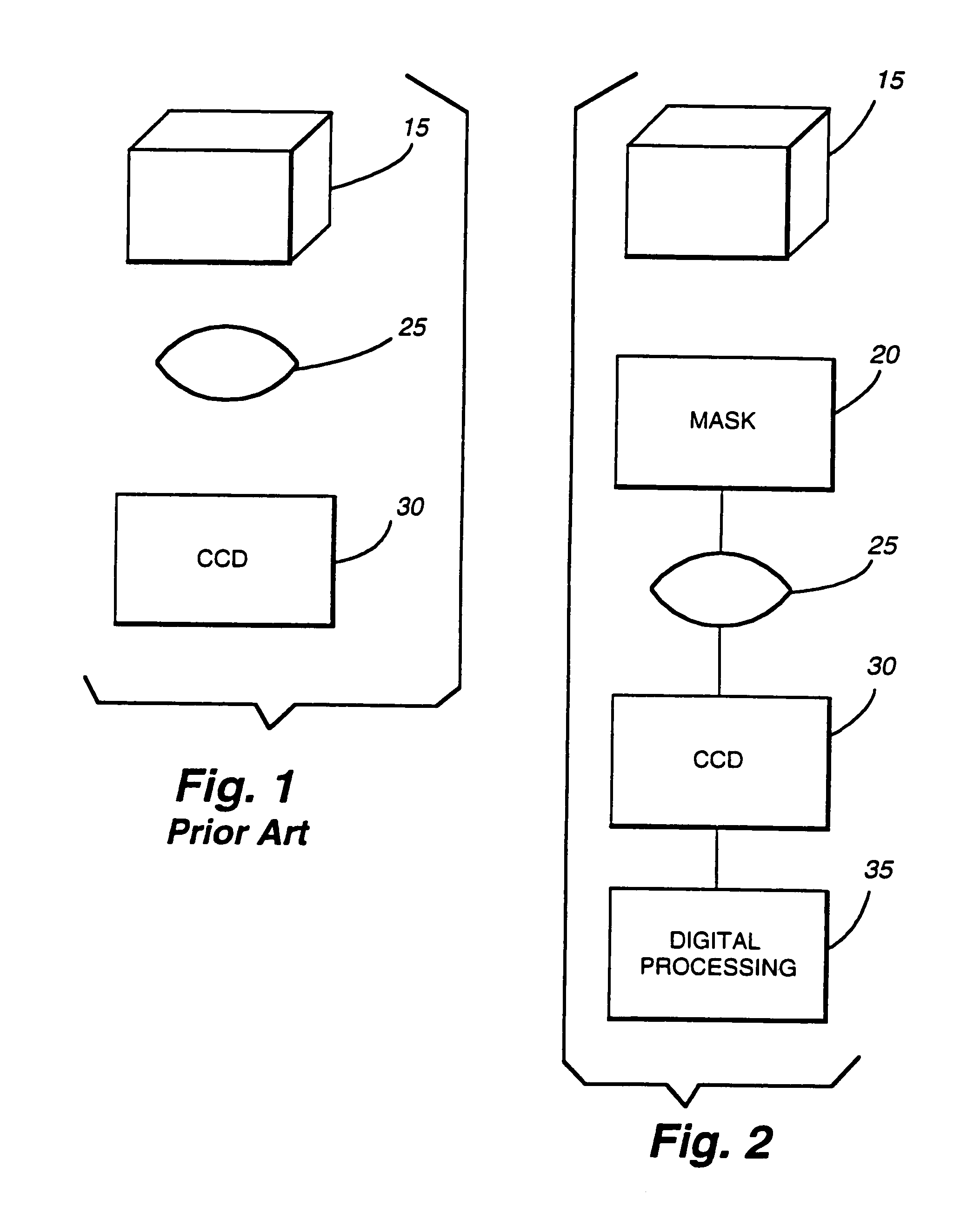
[0074]FIG. 1 (prior art) shows a standard optical imaging system. Object 15 is imaged through lens 25 onto Charge Coupled Device (CCD) 30. Such a system creates a sharp, in-focus image at CCD 30 only if object 15 is located at or very close to the in-focus object plane. If the distance from the back principal plane of lens 25 to CCD 30 is di, and focal length of lens 25 is f, the distance, d0, from the front principal plane of lens 25 to object 15 must be chosen such that:

[0075]1do+1di-1f=0

in order for the image at CCD 30 to be in-focus. The depth of field of an optical system is the distance the object can move away from the in-focus distance and still have the image be in focus. For a simple system like FIG. 1, the depth of field is very small.

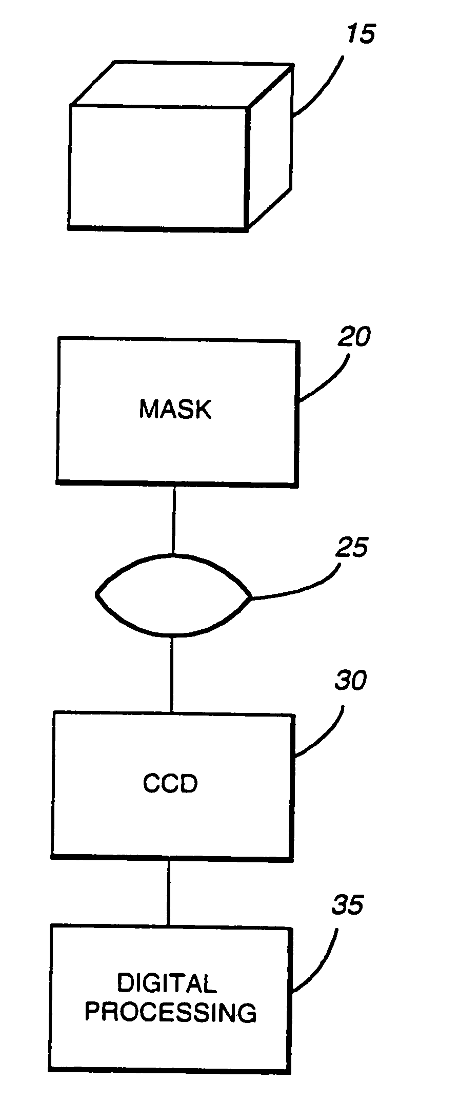
[0076]FIG. 2 shows the interaction and operation of a multi-component extended depth of field system in accordance with the invention. Object 15 is imaged through optical mask 20 and lens 25 onto Charge Coupled Device (CCD) system 30, and im...


PUM


Abstract

A system for increasing the depth of field and decreasing the wavelength sensitivity of an incoherent optical system incorporates a special purpose optical mask into the incoherent system. The optical mask has been designed to cause the optical transfer function to remain essentially constant within some range from the in-focus position. Signal processing of the resulting intermediate image undoes the optical transfer modifying effects of the mask, resulting in an in-focus image over an increased depth of field. Generally the mask is placed at or near an aperture stop or image of the aperture stop of the optical system. Preferably, the mask modifies only phase and not amplitude of light, though amplitude may be changed by associated filters or the like. The mask may be used to increase the useful range of passive ranging systems.

Description

CROSS-REFERENCE TO RELATED APPLICATIONS[0001]This application is a continuation in part of patent application Ser. No. 08 / 823,894 filed on Mar. 17, 1997 now U.S. Pat. No. 5,748,371 for Extended Depth of Field Optical Systems[0002]U.S. Pat. No. 5,521,695, issued May 28, 1996 and entitled “Range Estimation Apparatus and Method,” is incorporated herein by reference.[0003]This invention was made with Government support awarded by the National Science Foundation and the Office of Naval Research. The Government has certain rights in this invention.BACKGROUND OF THE INVENTION[0004]1. Field of the Invention[0005]This invention relates to apparatus and methods for increasing the depth of field and decreasing the wavelength sensitivity of incoherent optical systems. This invention is particularly useful for increasing the useful range of passive ranging systems. The same techniques are applicable to passive acoustical and electromagnetic ranging systems.[0006]2. Description of the Prior Art[0...

Claims


Application Information

Patent Timeline
IPC IPC(8): G02B5/18G06K9/40G01S3/783G02B5/00G02B27/00G02B27/46
CPCG01S3/7835G02B5/00G02B7/365G02B7/40G02B21/14G02B27/0025G02B27/46G02B27/52G01S11/12
Inventor CATHEY, JR., WADE THOMASDOWSKI, JR., EDWARD RAYMOND
Owner UNIV TECH
Why Eureka
Try Eureka