
Single/multiple axes six degrees of freedom (6 DOF) inertial motion capture system with initial orientation determination capability

a motion capture and inertial technology, applied in the field of motion sensing devices, can solve the problems of device disfavored, device development that has developed to sense these motion components, and large volume,

Inactive Publication Date: 2007-05-15
MAGNETO INERTIAL SENSING TECH
View PDF10 Cites 209 Cited by
  • Summary
  • Abstract
  • Description
  • Claims
  • Application Information

AI Technical Summary

Benefits of technology

The system provides accurate, real-time motion capture with minimal impact on the device's performance, is lightweight, low power, and cost-effective, enabling applications such as golf club swing analysis and full-body motion capture.

Problems solved by technology

The devices which have been developed to sense these motion components have, in the past, been rather bulky, high power, and expensive.
However, these devices have been disfavored because of their bulk, high power requirements, and high cost.
These more modern motion sensing devices, however, are still rather bulky and as a result, are often difficult to integrate into the device which is to be measured.
This is particularly problematic when there is a desire to measure the motion of a small, lightweight device, such as a piece of sports equipment where the addition of bulky hardware would change the nature of the movement or use of the device.
While the device of the '385 patent is capable of providing measured signals corresponding to three axes of freedom, it nevertheless does not provide rate information for overall motion of the device.
However, the device of the '380 patent fails to account for the directional signals typically provided by a gyroscope in other sensors, and thus, is not useful as a complete motion sensor component.
Further, the method of attachment of the various MEMS components does not provide a robust sensor capable of incorporation into items being measured.
The methods for minimizing noise and improving the quality of the motion captured signal taught in the '531 patent make this device impractical for motion capture applications involving higher rates of change.
This is particularly so given the delays which are necessarily implemented into the sensing circuitry to improve its noise tolerance, and thus make this device unresponsive for providing motion information for rapidly moving items.
While the device disclosed in the '846 patent may generate a motion-based signal that is measurable, it is woefully susceptible to external magnetic fields.
As a result, this device is not particularly useful in applications where the magnetic field may vary over time, or may vary between uses.

Method used


Image

  • Single/multiple axes six degrees of freedom (6 DOF) inertial motion capture system with initial orientation determination capability
  • Single/multiple axes six degrees of freedom (6 DOF) inertial motion capture system with initial orientation determination capability
  • Single/multiple axes six degrees of freedom (6 DOF) inertial motion capture system with initial orientation determination capability

Examples


Embodiment Construction

[0038]In a preferred embodiment, one motion capturing system of the present invention includes a motion sensing module, and microprocessor controlled interfaces which capture the motion data and analyze the data for real-time feedback, or for post-processing analysis. As will be discussed further below, there are numerous applications of the motion capture system of the present invention. However, in order to discuss these various applications, a basic discussion of the hardware of the present invention is provided.

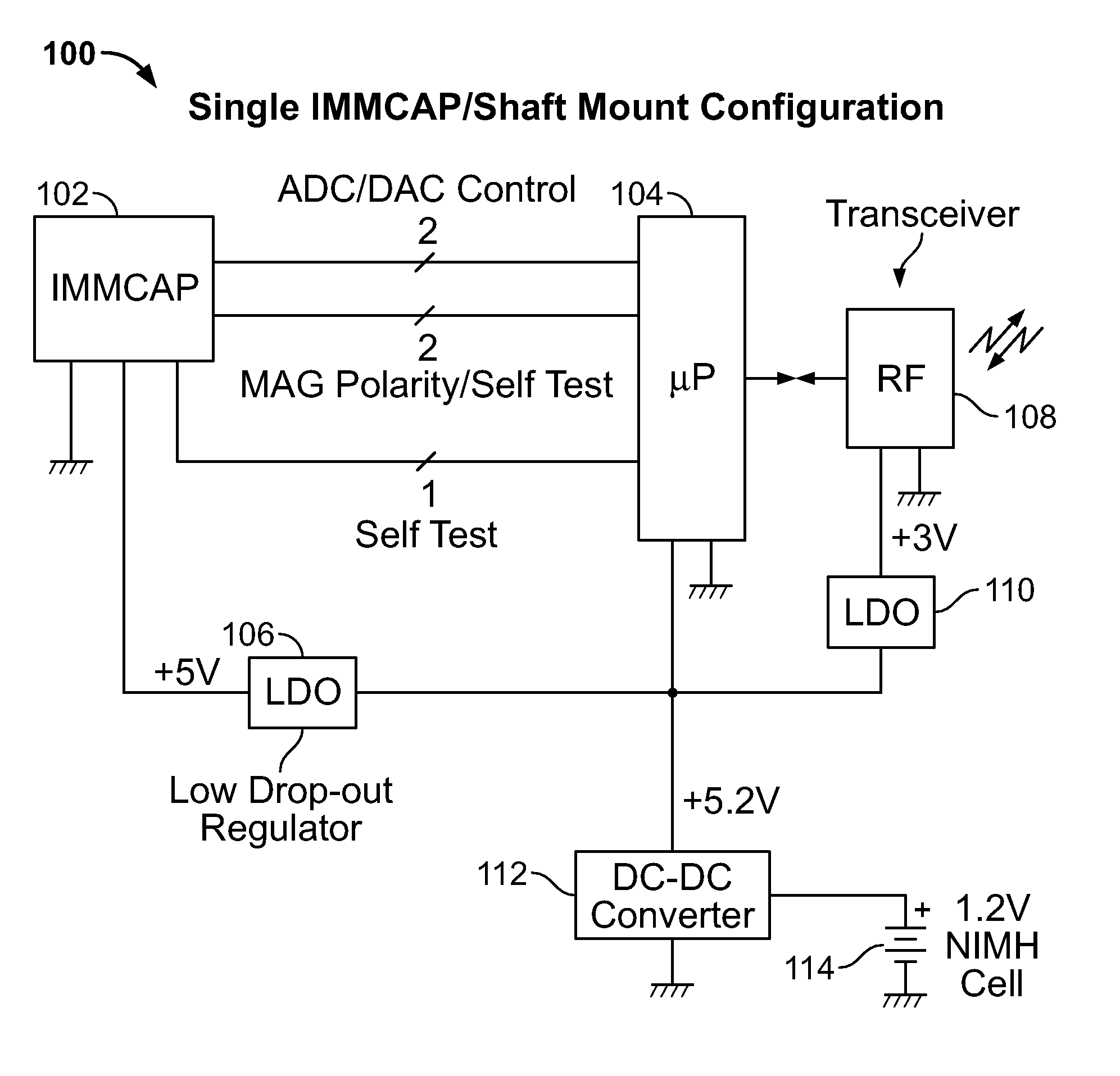
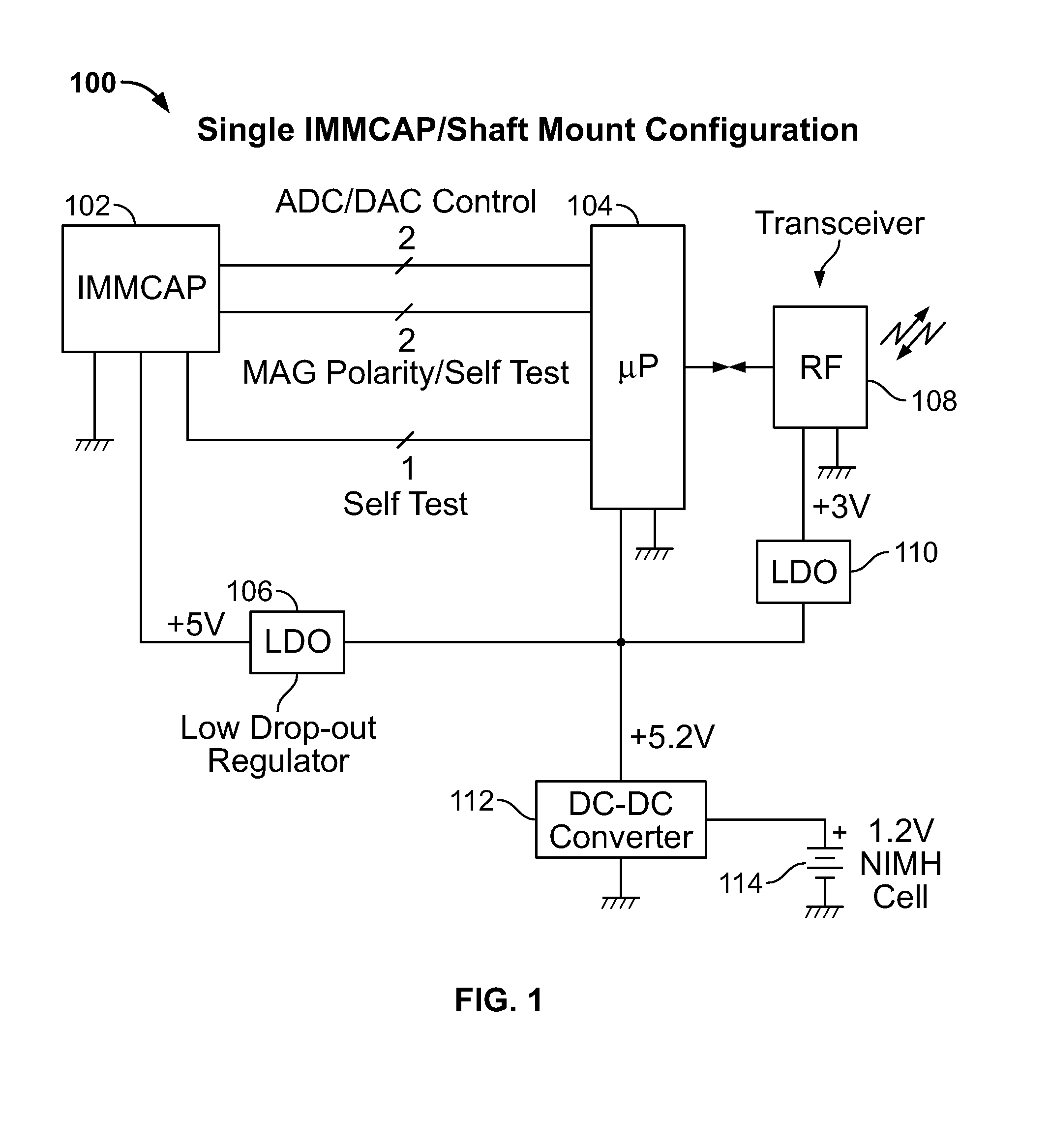
[0039]Referring initially to FIG. 1, a block diagram of a portion of the motion capture system of the present invention is shown and generally designated 100. Motion capture system 100 includes an inertial magnetic motion capture system (IMMCAP) module 102 in electrical connection with a microprocessor 104 which provides control signals to the module 102, and receives status information from the module 102 to facilitate proper operation. Analog output signals generated wi...


PUM


Abstract

A highly miniaturized electronic data acquisition system includes MEMS sensors that can be embedded onto moving device without affecting the static / dynamic motion characteristics of the device. The basic inertial magnetic motion capture (IMMCAP) module consists of a 3D printed circuit board having MEMS sensors configured to provide a tri-axial accelerometer; a tri-axial gyroscope, and a tri-axial magnetometer all in communication with analog to digital converters to convert the analog motion data to digital data for determining classic inertial measurement and change in spatial orientation (rho, theta, phi) and linear translation (x, y, z) relative to a fixed external coordinate system as well as the initial spatial orientation relative to the know relationship of the earth magnetic and gravitational fields. The data stream from the IMMCAP modules will allow the reconstruction of the time series of the 6 degrees of freedom for each rigid axis associated with each independent IMMCAP module.

Description

FIELD OF THE INVENTION[0001]The present invention relates generally to the field of motion sensing devices. The present invention is more particularly, though not exclusively, useful as a 6 Degree of freedom plus initial spatial orientation inertial motion measurement device for single / multiple axes applications for use in motion capture applications. The present invention is also useful for proving real-time analysis and feedback to a particular motion as compared to an optimal, or predetermined, motion.BACKGROUND OF THE INVENTION[0002]During recent years, there has been an increasing interest in the development of sophisticated devices capable of sensing the 6 degrees of freedom motion of a single or multiple axes rigid body in 3 dimensional space. The devices which have been developed to sense these motion components have, in the past, been rather bulky, high power, and expensive. For instance, in order to sense angular and linear motion, both gyroscopes and accelerometers have t...

Claims


Application Information

Patent Timeline
Patent Type & Authority Patents(United States)
IPC IPC(8): G01C17/00
CPCA63B59/0074G01C17/00G01C21/16A63B69/36A63B69/3632A63B71/0622A63B2024/0012A63B2024/0015A63B2069/0008A63B2071/0627A63B2220/12A63B2220/16A63B2220/40A63B2220/72A63B2220/80A63B2220/803A63B2220/833A63B2220/836A63B2225/50A63B60/46G01C19/00A63B60/42
Inventor KOLEN, PAUL T.
Owner MAGNETO INERTIAL SENSING TECH
Learn More