

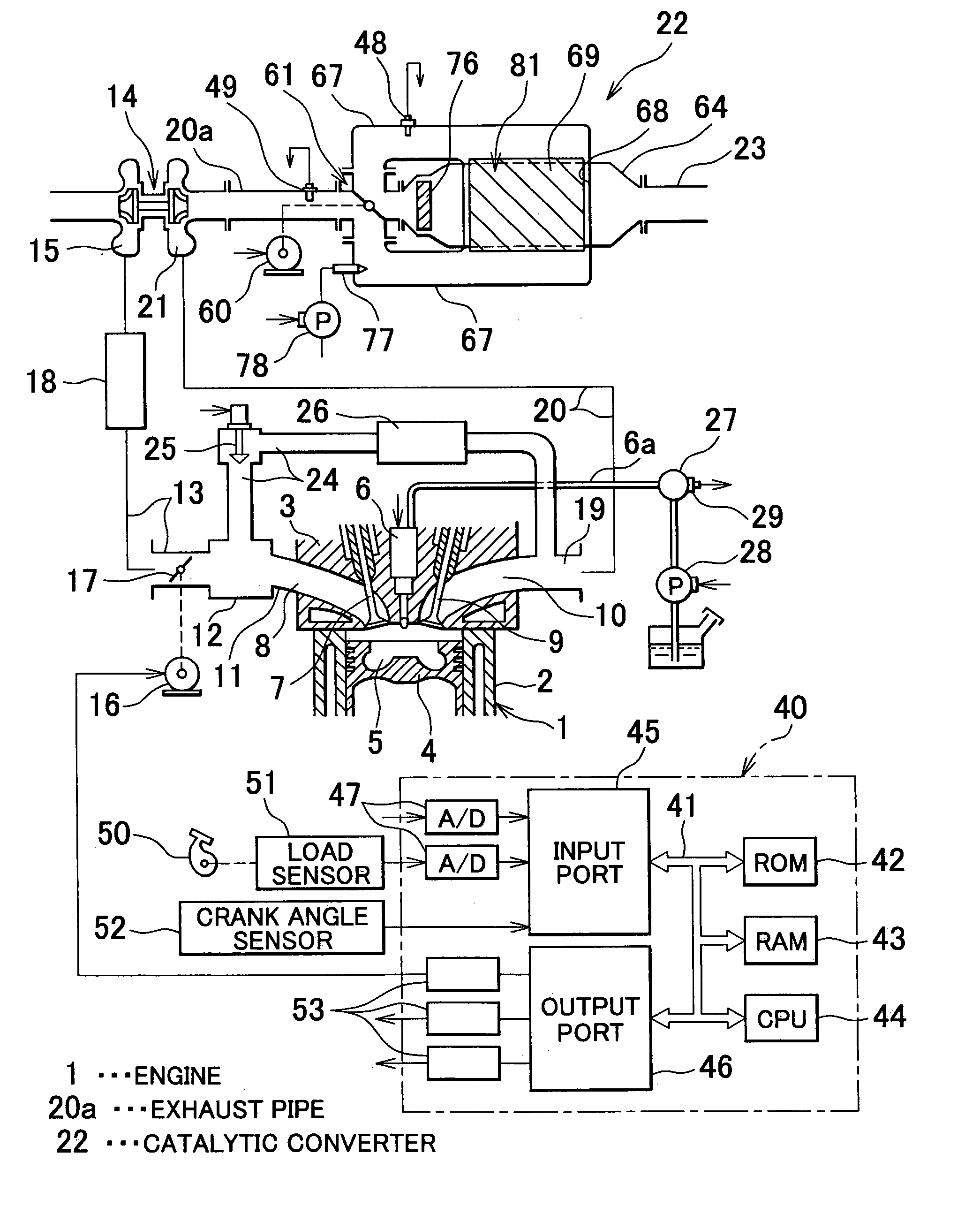
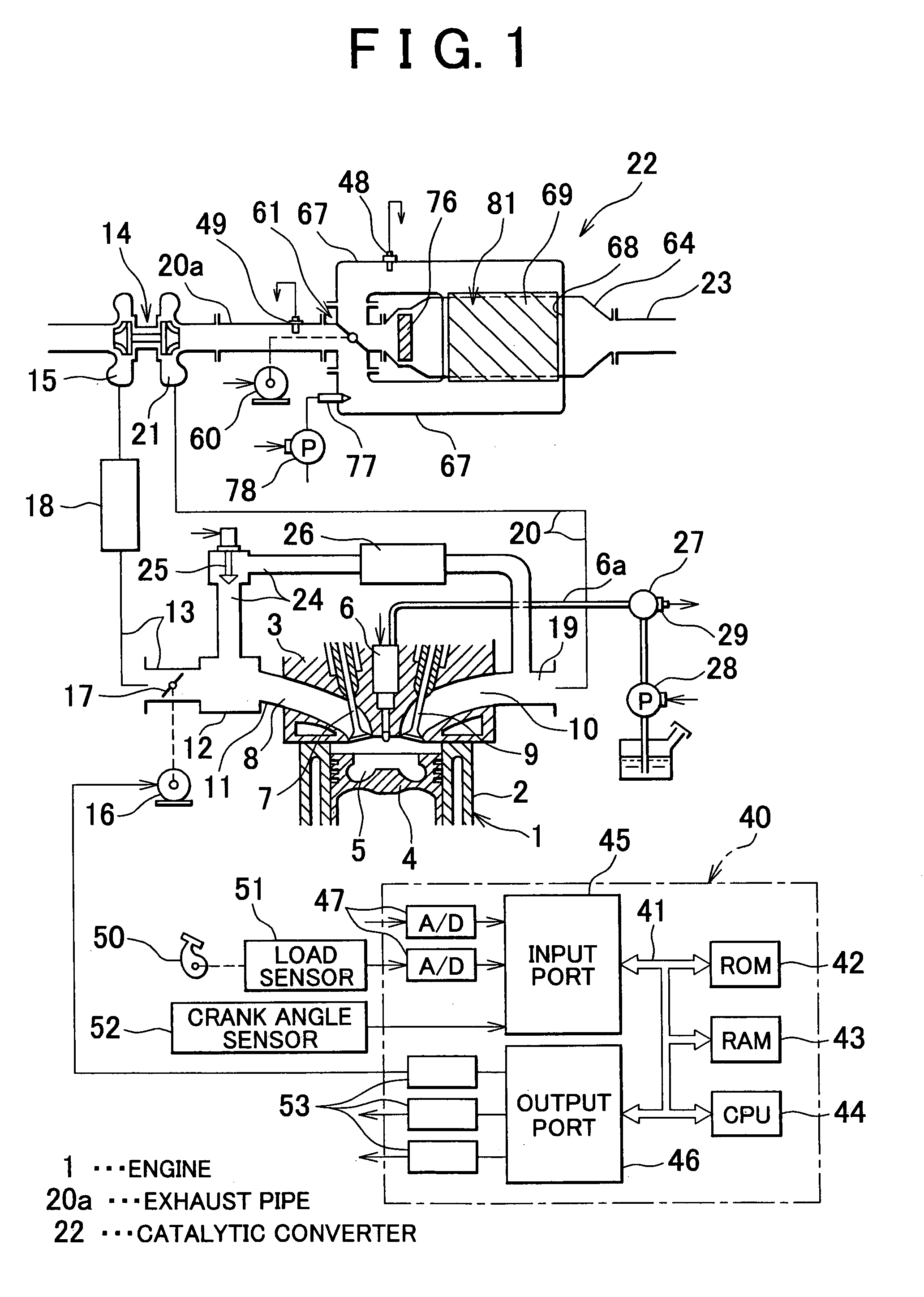
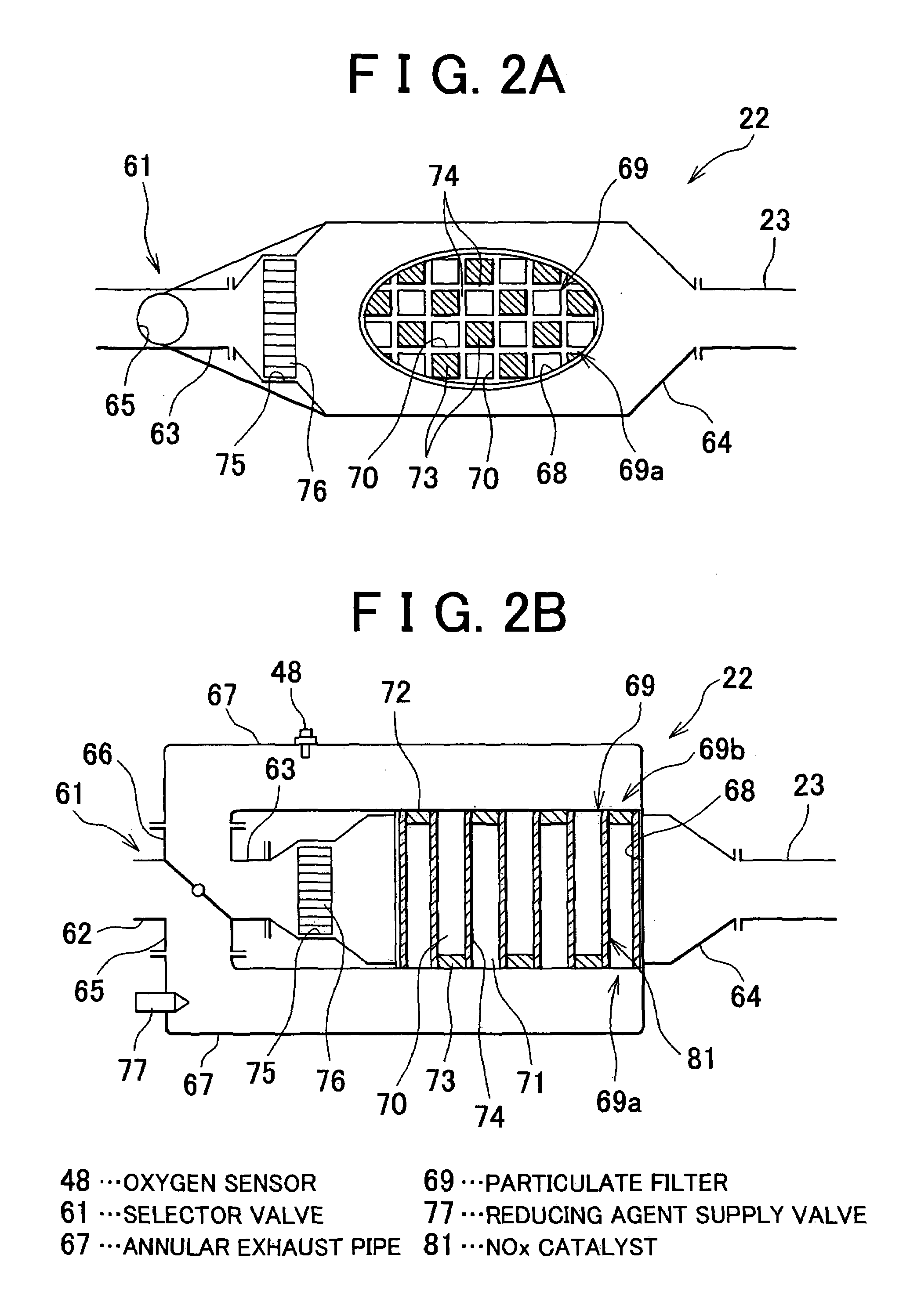
Exhaust emission control apparatus of internal combustion engine and method thereof
a technology of exhaust gas emission control and control apparatus, which is applied in mechanical apparatus, machines/engines, separation processes, etc., can solve the problems of >x /sub>catalyst to become larger or smaller, and the flow rate of exhaust gas flowing through
- Summary
- Abstract
- Description
- Claims
- Application Information
AI Technical Summary
Benefits of technology
Problems solved by technology
Method used
Image

Examples
first embodiment
[0104]In the control for correcting quantity of the reducing agent a reducing agent quantity correction coefficient KR is calculated for correcting the supply time period tFN under the control of reducing the stored NOX, and the supply time period tFS under the stored SOX reducing control such that the quantity of the reducing agent supplied through the reducing agent supply valve 77 becomes the normal quantity. That is, the supply time periods tFN and tFS are corrected using the correction coefficient KR (tFN=tFN·KR, tFS=tFS·KR). If the correction coefficient KR increases, both supply time periods tFN and tFS become long. If the correction coefficient KR decreases, both supply time periods tFS and tFS become short. The correction is not required, the correction coefficient KR is held at 1.0.
[0105]The correction coefficient KR is obtained in the following manner. In the first embodiment, in case of a predetermined engine operating state defined by, for example, the engine speed and...
second embodiment
[0121]In the control of correcting flow rate of the exhaust gas the coefficient KEX for correcting flow rate of the exhaust gas is calculated so as to correct the speed V for selecting the position of the selector valve 61 under the control of reducing the stored NOX. That is, the speed V is corrected with the coefficient KEX (V=V·KEX). If the coefficient KEX increases, the speed V becomes higher. If the coefficient KEX decreases, the speed V becomes lower. As the selector valve 61 is driven by the stepping motor 60, the speed V for selecting the position of the selector valve 61 is variable.
[0122]More specifically, the time tP elapsing from the timing X until timing when the output OP of the oxygen sensor 48 reaches a peak is obtained at every execution of the control of reducing the stored NOX (see FIG. 7). If the actual time period tC elapsing from the timing X until the timing at which the reducing agent is supplied is longer than the normal time period, the space velocity of t...
third embodiment
[0131]In the third embodiment, in the condition where OPA>OPAT, the coefficient KEX is decreased, and in the condition where OPA0 is also updated (D=D·KEX). The condition where OPA=OPAT represents that the correction coefficient KEX used herein is the final correction coefficient.
[0132]Under the control of reducing the stored SOX, the reducing agent is supplied while holding the opening degree D of the selector valve 61.
[0133]A flowchart in FIG. 18 represents the control routine for correcting the flow rate of the exhaust gas according to the third embodiment. The routine of the third embodiment is executed as shown in FIGS. 13 to 15. The control routine for correcting the flow rate of the exhaust gas shown in FIG. 18 is executed in step 233 of the correction control routine shown in FIG. 14.
[0134]Referring to FIG. 18, in step 270, it is determined whether the control routine for reducing the stored NOX has been executed, that is, the reducing agent has been supplied through the red...
PUM
 Abstract
Description
Claims
Application Information