Compact, high-efficiency illumination system for video-imaging devices

a video-imaging device, high-efficiency technology, applied in the direction of lighting and heating apparatus, mechanical equipment, instruments, etc., can solve the problems of ineffective image optics, insufficient light coupling efficiency, and needing a long air gap, so as to increase the efficiency of illumination system, and increase the efficiency of light coupling

Inactive Publication Date: 2007-05-22
ADVANCED LIGHTING TECH +1
View PDF8 Cites 14 Cited by
  • Summary
  • Abstract
  • Description
  • Claims
  • Application Information

AI Technical Summary

Benefits of technology

[0008]By employing non-imaging optics, the illumination systems for video-imaging devices described herein overcome many problems of the prior art systems based on imaging optics, Fiberstars Inc., of Solon, Ohio, the present assignee, has successfully used non-imaging optics as a basis for large increases in illumination system efficiency, such as with its Product No. EFO-4+4-NC-120. Fiberstars Inc. has increased light coupling efficiency by 30% for fixtures using non-imaging optics compared to those that use imaging optics. Fiberstars Inc. has also made fiber optics systems that are 200-400% more efficient than the imaging optics-based fiber optics systems produced up through about the year 2000.
[0013]One embodiment of the invention provides an illumination system for a video-imaging device having a light source and a collector of light from the light source. The collector is formed according to the principles of non-imaging optics and receives a portion of the light from the light source. The collector is configured to reduce the angular distribution of the collected light from the light source to match the requirements of a digital pixelation device. This system is highly efficient and compact compared to systems based on imaging optics, and can eliminate some of the components required for systems based on imaging optics.

Problems solved by technology

Imaging optics have disadvantages in that (1) they are inherently inefficient, (2) they preserve artifacts of the light source (such as very bright or very dim regions), and (3) they are large and often need a long air gap between the light source and the digital pixelation device.
Too broad a spread will result in light “bleeding” through from pixel to pixel, which affects the overall quality of the picture—especially in dark sections.
Too narrow a distribution can be a problem when it is desired to make the image viewable at wide angles to the screen.

Method used


Image

  • Compact, high-efficiency illumination system for video-imaging devices
  • Compact, high-efficiency illumination system for video-imaging devices
  • Compact, high-efficiency illumination system for video-imaging devices

Examples


Embodiment Construction

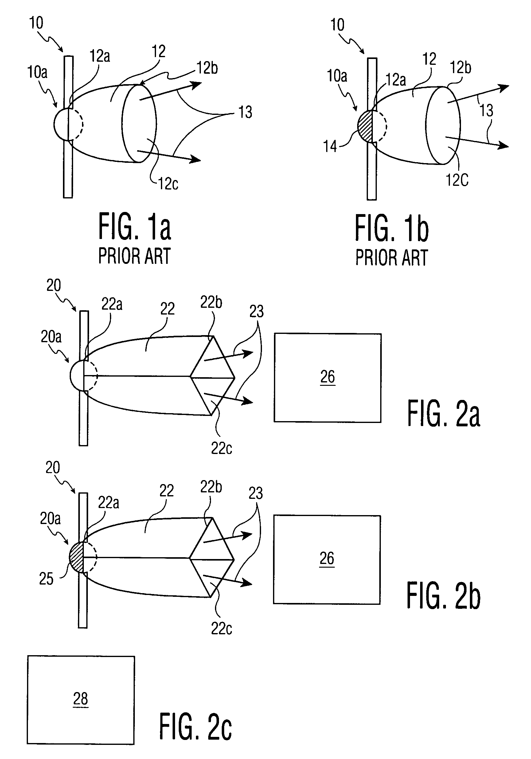
[0024]To put the present illumination system for video-imaging devices in perspective, the prior art lighting devices of FIGS. 1a and 1b, not used for illuminating video-imaging devices, are first considered. FIG. 1a shows a light source 10, such as a metal halide discharge lamp. A bulbous section, or arctube, 10a of the lamp extends into an inlet 12a of a non-imaging light-collector 12. Collector 12 performs an angle-to-area conversion on light from source 10, reducing the angle of light 13 to a lower half angle, such as 38 degrees, for reception by a light pipe (not shown), for instance. Inlet12a of the collector, and outlet 12b of the collector, are both round or oval. The collector shown is hollow, and has an interior reflective coating 12c. Prior art FIG. 1b is similar to FIG. 1a but shows a mirror coating 14 on about one hemisphere of arctube 10a of the lamp, for reflecting visible light through the other hemisphere and into collector 12. U.S. Pat. No. 6,304,693 for Efficient ...


PUM


Abstract

An illumination system for a video-imaging device has a light source and a collector of light from the light source. The collector is formed according to the principles of non-imaging optics and receives a portion of the light from the light source. The collector is configured to reduce the angular distribution of the collected light from the light source to match the requirements of a digital pixelation device.

Description

[0001]This application claims priority from U.S. Provisional Patent Application No. 60 / 452,821 filed Mar. 17, 2003.FIELD OF THE INVENTION[0002]The present invention relates to a compact and more efficient illumination system for video imaging devices. More particularly, the invention relates to the use of non-imaging optics and a high intensity light source to provide enough light at the proper angular distribution for video imaging devices to more fully take advantage of the efficiencies inherent in high intensity discharge devices.BACKGROUND OF THE INVENTION[0003]Modern video-imaging systems use high brightness lamps to transmit an image either through, or reflected from, a small digital pixelation device. As used herein, a “digital pixelation device” (“DPD”) can comprise many small mirrors, a liquid crystal display (LCD), or one of many other concepts being developed for video-imaging devices. For instance, Texas Instruments, of Dallas, Tex., has developed digital light processin...

Claims


Application Information

Patent Timeline
Patent Type & Authority Patents(United States)
IPC IPC(8): F21V7/04F21V8/00G02B6/00G02B6/42G02B17/06G02B27/09
CPCG02B6/0096G02B27/0994G02B19/0071G02B19/0023G02B19/0047G02B6/0001G02B6/4296G02B6/4298
Inventor BUELOW, II, ROGER F.HELLMAN, WAYNE R.SULCS, JURISDAVENPORT, JOHN M.BUCHINA, RAYMOND A.FRANKIEWICZ, GREGORY P.
Owner ADVANCED LIGHTING TECH
Why Eureka
Try Eureka