Light source device and light polarizing element

light polarizing element technology, applied in the field of light source devices and light polarizing elements, can solve the problems of insufficient narrowing or extremely narrowing of the distribution of outgoing light from the light guide, and the practicality of a light source device with a relatively large size is inferior, and achieves small reduction of luminance, improved luminance, and high light condensing effect.

Inactive Publication Date: 2007-05-22
LMS
View PDF19 Cites 22 Cited by
  • Summary
  • Abstract
  • Description
  • Claims
  • Application Information

AI Technical Summary

Benefits of technology

[0009]It is therefore an object of the present invention to provide a light source device that can achieve improvement in luminance by a high light-condensing effect, that is small in reduction of luminance with respect to a change in viewing direction, that enables improvement in utilization efficiency of the quantity of light emitted from a primary light source (i.e. increases efficiency of emitting light, which is emitted from a primary light source, concentratedly in a required viewing direction), and further, that can easily improve the image quality with a simplified structure.
[0018]According to the present invention, both prism faces of each of elongated prisms formed at a light receiving surface of a light deflection element are each formed by faces such as a plurality of flat faces, convex curved faces, or the like having different inclination angles so that it is possible to provide a light source device that can achieve improvement in luminance by a high light-condensing effect, that is small in reduction of luminance with respect to a change in viewing direction, that enables improvement in utilization efficiency of the quantity of light emitted from a primary light source (i.e. increases efficiency of emitting light, which is emitted from a primary light source, concentratedly in a required viewing direction), and further, that can easily improve the image quality with a simplified structure.

Problems solved by technology

However, such a light source device has a problem that although the concentrated emission in the narrow angle range is enabled, an outgoing light distribution is extremely narrow so that a large reduction in luminance is caused only by a small change in viewing direction, thereby being inferior in practicality in case of a light source device with a relatively large size.
This formation is complicated.
However, since the convex curved surface shaped prism faces described in those publications each have a radius of curvature that is relatively larger or relatively smaller, a distribution of the outgoing light from the light guide cannot be sufficiently narrowed or is extremely narrowed or, according to circumstances, is conversely broadened.
Further, in any of the light guides described in those publications, a light emitting function structure thereof cannot achieve a high directivity so that light of which an outgoing light distribution is relatively broad is emitted, and therefore, it is not possible to sufficiently improve the luminance even by condensing the light using the prism sheet.

Method used


Image

  • Light source device and light polarizing element
  • Light source device and light polarizing element
  • Light source device and light polarizing element

Examples


examples 1 to 9

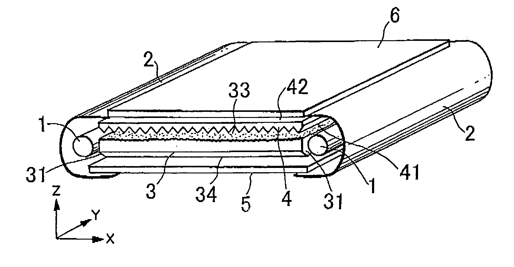
[0087]Using an acrylic resin (Acrypet VH5#000 produced by Mitsubishi Rayon Co., Ltd.), there were prepared, by injection molding, 14-inch light guides each having a size of 210 mm×300 mm with a thickness of 6 mm. Each light guide had one surface in the form of a mat having an average inclination angle of 8 degrees and the other surface having elongated prisms successively arrayed parallel to each other at a pitch of 50 μm and with a prism vertical angle of 100 degrees and each extending perpendicular to sides each having a length of 300 mm (long sides) of the light guide. Cold-cathode tubes were disposed along both side end surfaces corresponding to the sides of 300 mm (long sides) of the light guide, while the cold-cathode tubes were each covered with a light source reflector (silver reflection film produced by Reikosha) Further, light diffusion reflection films (E60 produced by Toray Industries, Inc.) were stuck to the other side end surfaces, and a reflection sheet was disposed o...

example 10

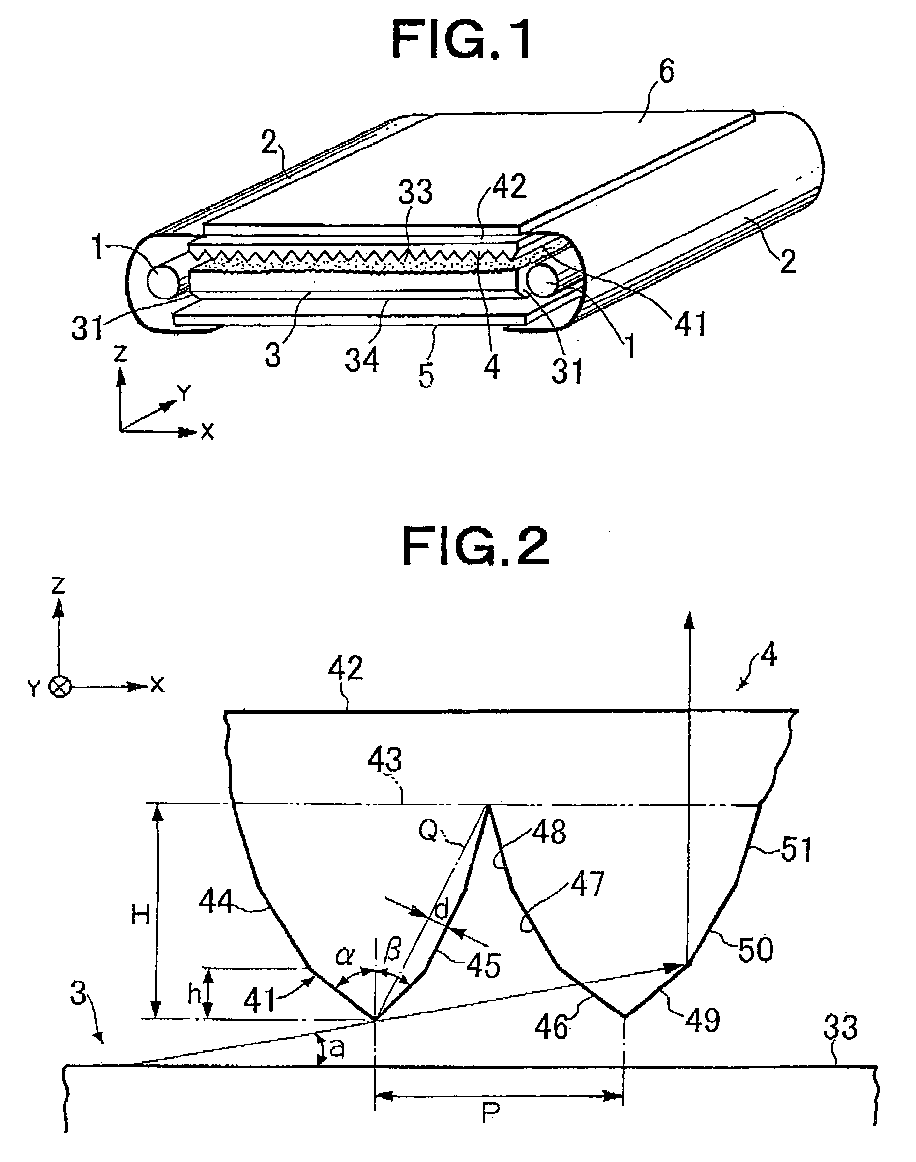
[0093]A prism sheet was prepared like in Example 1 except that, as shown in Table 2, each of both prism faces forming each elongated prism was formed by two flat faces (areas 1 and 2 from the side of the prism vertex portion), i.e. a flat face (β=32.0 degrees) formed from the prism vertex portion to a height 17.1 μm (h′) of the elongated prism and having an inclination angle of 58.0 degrees, and a flat face formed from and above the height 17.1 μm of the elongated prism and having an inclination angle of 62.0 degrees.

[0094]The obtained prism sheet was placed such that the elongated-prism formed surface was oriented toward the light outgoing surface of the same light guide as in Example 1 and the prism ridgelines were parallel to the light incident surfaces of the light guide, thereby obtaining a surface light source device. There was derived an outgoing light luminance distribution (in the XZ-plane) in the plane perpendicular to both the light incident surface and the light outgoing...

example 11

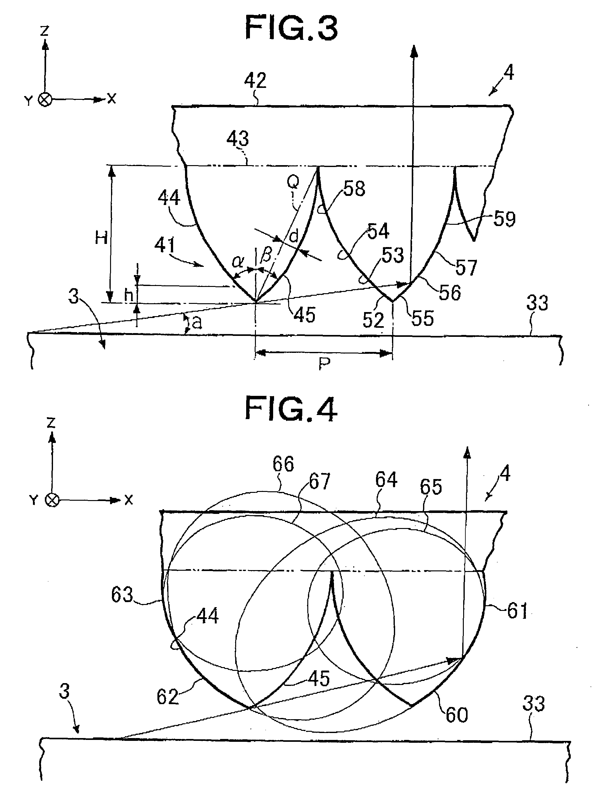
[0095]A prism sheet was prepared like in Example 1 except that, as shown in Table 2, each of both prism faces forming each elongated prism was formed by two flat faces (areas 1 and 2 from the side of the prism vertex portion), i.e. a flat face (β=32.0 degrees) formed from the prism vertex portion to a height 17.1 μm (h′) of the elongated prism and having an inclination angle of 58.0 degrees, and a flat face formed from and above the height 17.1 μm of the elongated prism and having an inclination angle of 60.0 degrees.

[0096]The obtained prism sheet was placed such that the elongated-prism formed surface was oriented toward the light outgoing surface of the same light guide as in Example 1 and the prism ridgelines were parallel to the light incident surfaces of the light guide, thereby obtaining a surface light source device. There was derived an outgoing light luminance distribution (in the XZ-plane) in the plane perpendicular to both the light incident surface and the light outgoing...


PUM


Abstract

A light source device, comprising a light guide (3) having two light incident surfaces opposed to each other for receiving incident light radiated from a primary light source and a light outgoing surface (33) for emitting the incident light and a light deflection element (4) disposed adjacent to the light emitting surface side of the light guide, the light deflection element (4) further comprising a light receiving surface (41) for receiving incident light and a light emitting surface (42) positioned on the opposite side thereof and emitting the incident light, wherein a plurality of elongated prisms formed of two prism faces are disposed on the light receiving surface (41) generally parallel with each other, the prism surfaces are formed of at least two faces (46, 47, 48, 49, 50, 51) with different inclination angles, and the inclination angles are larger for the faces positioned nearer the light emitting surface (42).

Description

TECHNICAL FIELD[0001]The present invention relates to an edge-light type light source device constituting a liquid crystal display device or the like that is used as a display portion of a notebook personal computer, a liquid crystal television, a portable telephone, a portable information terminal, or the like and to a light deflection element for use in the light source device and, in particular, relates to a light source device that is suitably used in a liquid crystal display device or the like with a relatively large size, has primary light sources disposed facing two opposite side end surfaces of a light guide, respectively, and can achieve an extremely high luminance without causing a large reduction in luminance due to a change in viewing direction, and to a light deflecting element for use in such a light source device.BACKGROUND ART[0002]In recent years, color liquid crystal display devices have been widely used in various fields as monitors of portable notebook personal c...

Claims


Application Information

Patent Timeline
Patent Type & Authority Patents(United States)
IPC IPC(8): F21V7/04F21V8/00
CPCG02B6/0038G02B6/0053G02B6/0051G02B5/02G02B5/04G02B6/0001G02F1/1335
Inventor YAMASHITA, TOMOYOSHICHIBA, ISSEI
Owner LMS
Why Eureka
Try Eureka