Method and apparatus for the measurement and control of both the inside and outside surface temperature of thermoplastic preforms during stretch blow molding operations

a technology of stretch blow molding and temperature measurement, applied in the direction of optical radiation measurement, electric/magnetic/electromagnetic heating, instruments, etc., can solve the problem of limited state-of-the-art implementation, and limited application of process information related to critical control parameters (e.g., inside and outside preform temperature). problem, to achieve the effect of optimizing the stretch blow molding process or energy consumption efficiency, minimizing maintenance time, and minimizing

Active Publication Date: 2007-05-22
PRESSCO IP LLC
View PDF8 Cites 28 Cited by
  • Summary
  • Abstract
  • Description
  • Claims
  • Application Information

AI Technical Summary

Benefits of technology

[0016]Another object of this invention is to provide a blow molding system with a temperature measurement and control system capable of making measurements on individual preforms as they dynamically move towards the blow molding operation, eliminating the need to make control decisions based on average preform temperature measurements.
[0019]Another aspect of this invention is to provide a way of correlating or linking the specific heat measurements to subsequent quality or process measurements after blowing to best optimize the stretch blow molding process or energy consumption efficiency.
[0020]Another aspect of this invention is to directly relate specific machine components such as molds, spindles, and lamps to specific thermal data and profiles to minimize maintenance time and to optimize manufacturing system performance.

Problems solved by technology

The state-of-the-art implementations, as described in, for example, the noted patents, are limited to providing an averaged automated process control measurement on the outside surface temperature of the preform, exclusively.
Process information related to critical control parameters (e,g., inside and outside preform temperature) has been limited in scope due to existing limitations in infrared temperature measurement technology and methodology.
A significant limitation of pyrometers, though, is that their response time is relatively slow.
In a dynamic blow molding system, the rate at which preforms are transported through the system does not allow for the accurate temperature measurement of any one preform using a pyrometer.
One limitation of this sampling scheme is that significant preform to preform temperature variations, if present, are averaged out and go undetected by the process control apparatus deployed in prior art machines.
This time period is much too short to allow pyrometers to make an accurate temperature measurement.
Direct contact methods for measuring temperatures, such as thermocouples, are impractical because of speed limitations and because such devices may cause damage to the hot pliable preform.
If such damage occurred, it would undesirably render the process a high maintenance endeavor.
An additional and perhaps more severe limitation related to the slow response time of pyrometers is that that there has been no direct practical manner discovered by which a reasonable and accurate measurement of the inside surface temperature of moving preforms can be obtained using these devices.
Indirect methods, using complex thermal conduction equations and multiple, time spaced pyrometers, have been theorized but have not been implemented into factory production systems.
The difficulty of implementing, maintaining, and calibrating such systems is a serious drawback.
Further, such systems only predict from indirect measurements—which allows uncontrolled environmental and other variables to adversely affect the temperature estimates and create inaccuracy and mistrust of such estimates.

Method used


Image

  • Method and apparatus for the measurement and control of both the inside and outside surface temperature of thermoplastic preforms during stretch blow molding operations
  • Method and apparatus for the measurement and control of both the inside and outside surface temperature of thermoplastic preforms during stretch blow molding operations
  • Method and apparatus for the measurement and control of both the inside and outside surface temperature of thermoplastic preforms during stretch blow molding operations

Examples


Embodiment Construction

[0027]An objective of this invention is to provide a blow molding system having an improved thermal conditioning section with improved temperature measurement and control features. The temperature measurement and control features enable the system to directly monitor one or both of the outside and inside surface temperatures of preforms at different stages of transport throughout the thermal conditioning section of the system. That is, the present invention implements a methodology for the direct and precise measurement of individual preforms and selected sub-portions thereof. This advancement in the art was not heretofore known and provides significant advantages in the blow molding field.

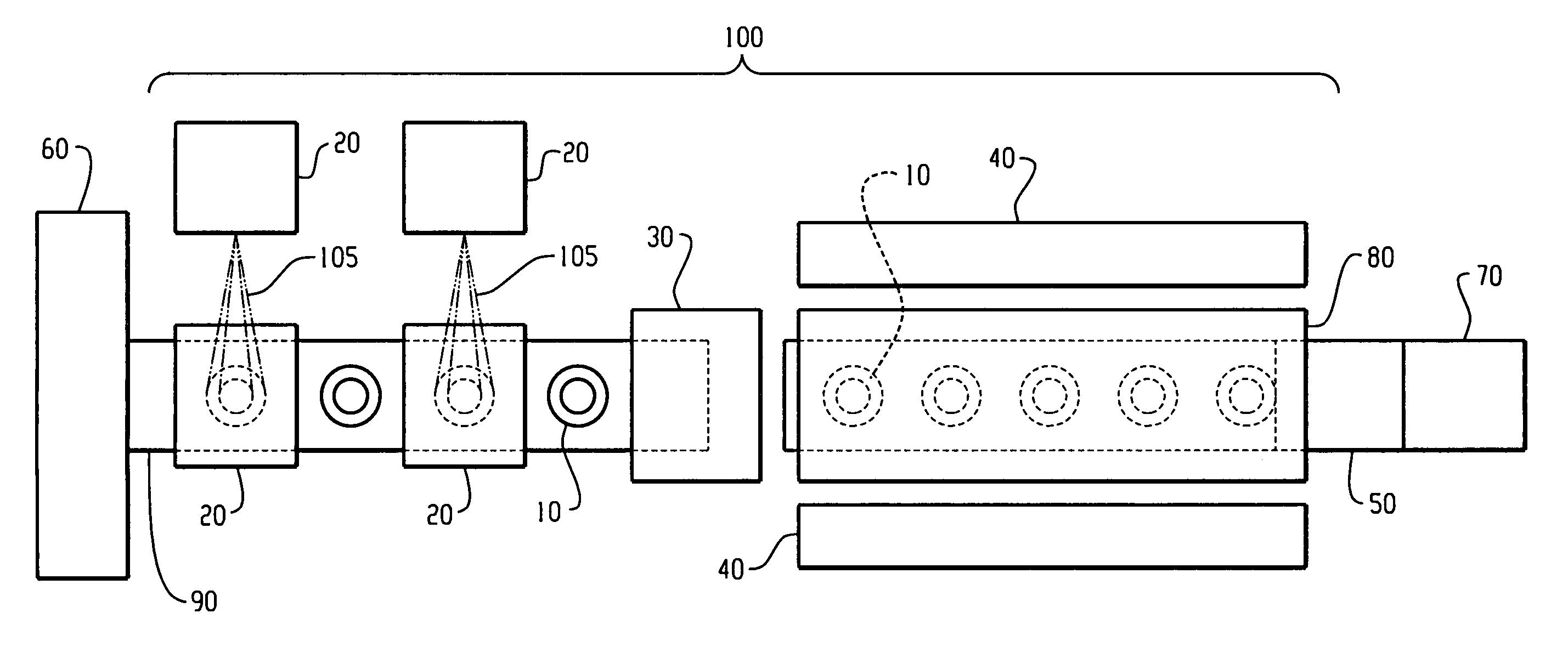
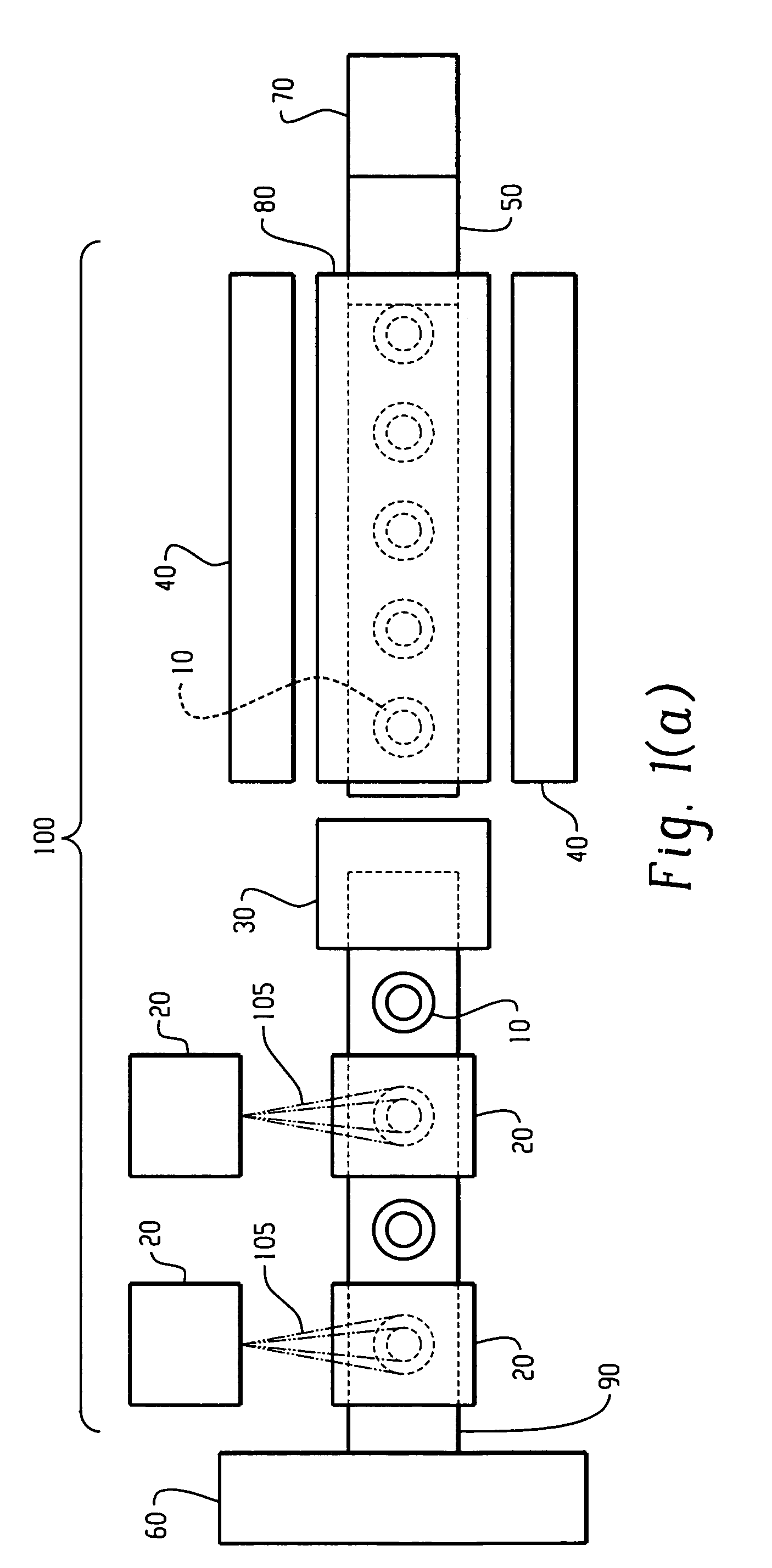
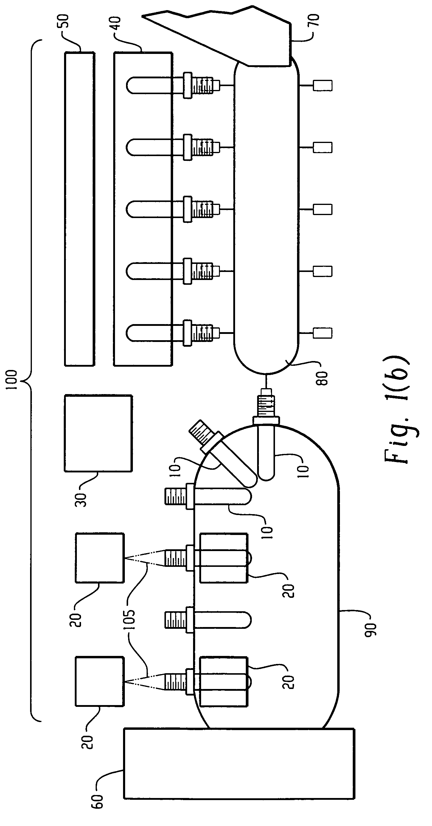
[0028]Referring to FIGS. 1(a) and (b), the components of a thermal conditioning section 100 include high-speed infrared temperature sensors 20 and an infrared temperature processing and control subsystem 30. The infrared temperature processing and control subsystem 30 interfaces directly with the ...


PUM

PropertyMeasurementUnit
temperatureaaaaaaaaaa
operating temperatureaaaaaaaaaa
chop frequencyaaaaaaaaaa

Abstract

A stretch blow molding system that condition preforms such that the temperature distribution within the cross-section of each preform is optimized prior to blow molding operations is provided. The system has a temperature measurement and control system capable of directly monitoring both the outside as well as inside surface temperature of preforms at different stages of transport throughout the thermal conditioning section of the system.

Description

BACKGROUND OF THE INVENTION[0001]This invention is directed to blow molding systems. More specifically, it is directed to stretch blow molding systems that condition preforms such that the temperature distribution within the cross-section of each preform is optimized prior to blow molding operations.[0002]By way of background, one of the most critical process variables when attempting to stretch blow mold certain materials is the temperature distribution of the preform as it is being blown. This variable often has a significant impact on the most important physical properties of the final blown article. Ideally, the preform wall cross-sectional temperature distribution should be optimized for blow molding operations. In addition, it is advantageous within an automated blow molding process if preforms that are moving through the system are consistent in temperature profile, one preform to the next. In more specific terms, it is advantageous for both the inside and outside surface tem...

Claims


Application Information

Patent Timeline
Patent Type & Authority Patents(United States)
IPC IPC(8): B29C49/64B29C49/78B29C49/06
CPCB29C49/78G01J5/061G01J5/62B29C49/06G01J5/0805B29C2949/0715B29C2049/7861B29C2049/78805
Inventor COCHRAN, DON W.CECH, STEVEN D.
Owner PRESSCO IP LLC
Why Eureka
Try Eureka