Capacitor of magnetron

a technology of capacitor and magnetron, applied in the field of magnets, can solve the problems of capacitor for the conventional magnetron, the outer electrode is formed to have an undetectedly large surface area compared to the inner electrode, and the capacitor is increased, so as to reduce the time for manufacturing products, reduce the size, and excellent resistance to voltage and capacitance.

Active Publication Date: 2007-05-22
LG ELECTRONICS INC
View PDF2 Cites 4 Cited by
  • Summary
  • Abstract
  • Description
  • Claims
  • Application Information

AI Technical Summary

Benefits of technology

[0041]An object of the present invention is to provide a capacitor of a magnetron, designed to have excellent withstand voltage and capacitance, and to have a reduced size and a filling amount of epoxy resin, thereby reducing the time for manufacturing products employing the magnetron.

Problems solved by technology

However, the capacitor for the conventional magnetron has problems as follows.
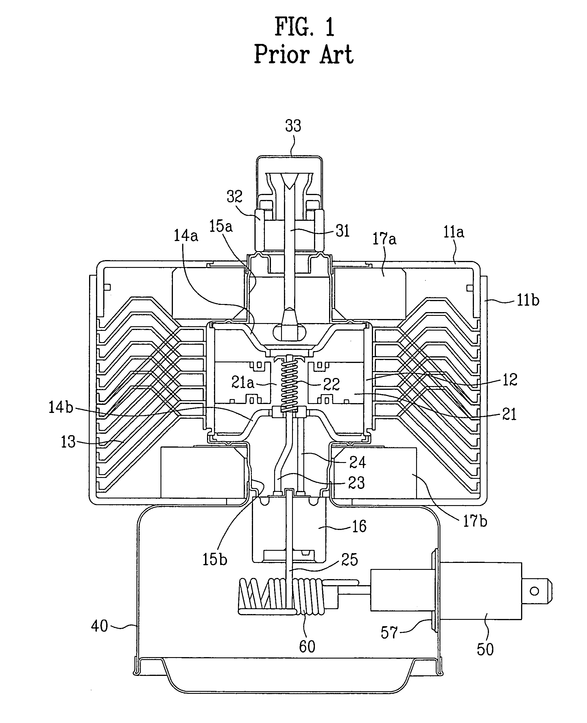
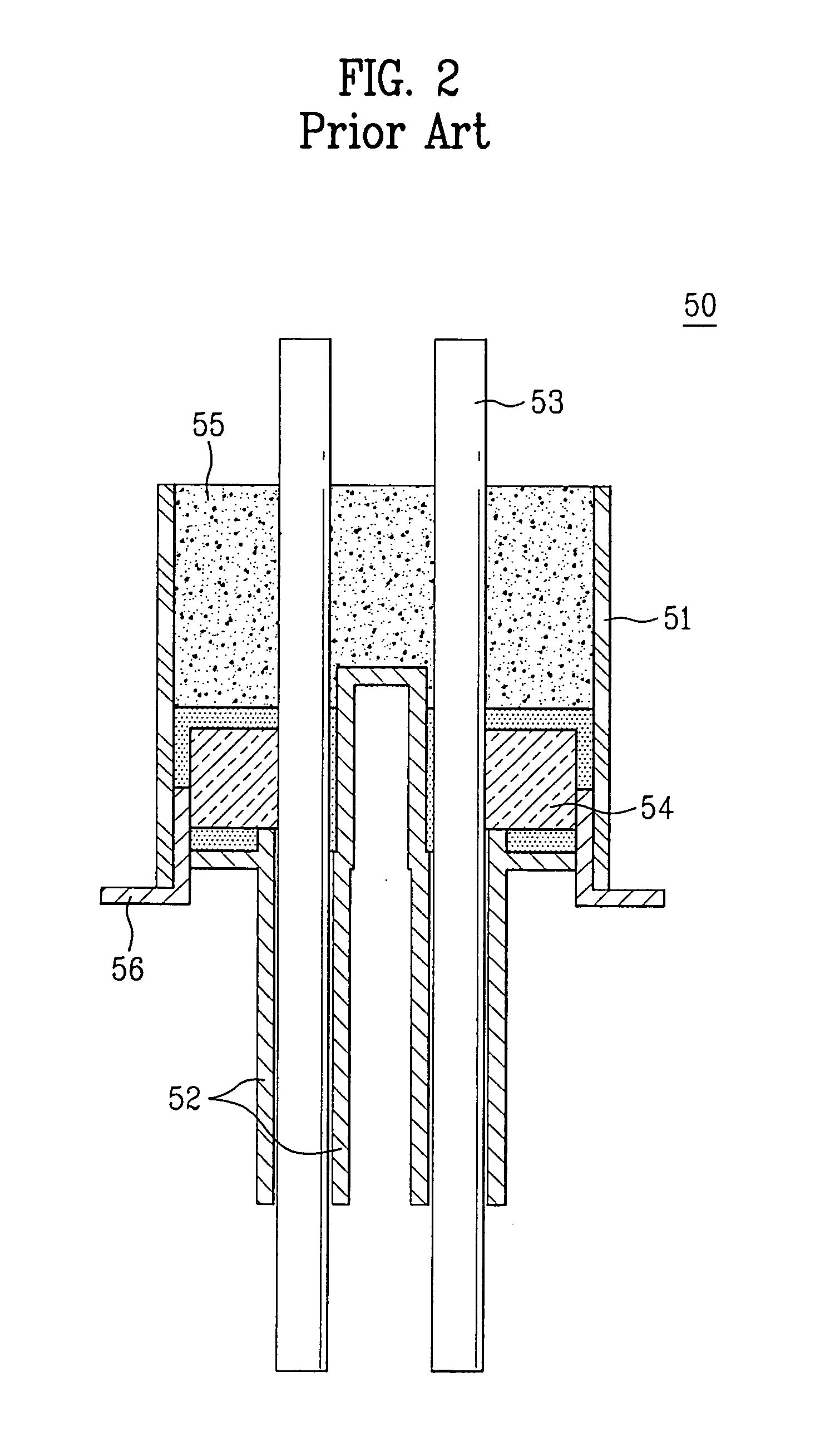
Firstly, although the dielectric members are formed to have the semicircular shapes in order to increase the effective surface areas of the dielectric members, the outer electrode is formed to have an undesirably enlarged surface area compared to that of the inner electrode.
Thus, the size, in particular, a width W, of the capacitor is increased, and the amount of epoxy resin required to fill the insulating case is undesirably increased, thereby increasing the time for curing the epoxy resin.
As a result, there are problems of increasing a time for manufacturing the products, a price of the products, and the size of the capacitor.
In this case, costs for manufacturing the central conductors are increased, so that the sizes of the central conductors and the capacitor are increased together with an increase of a filling amount of the epoxy resin.

Method used


Image

  • Capacitor of magnetron
  • Capacitor of magnetron
  • Capacitor of magnetron

Examples


first embodiment

[0067]the dielectric members will be described with reference to FIG. 7.

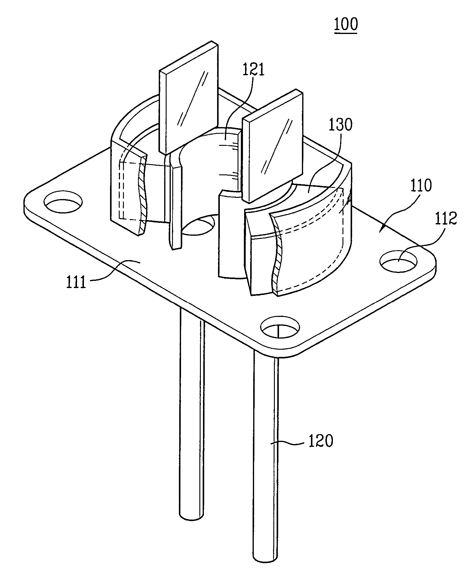
[0068]The inner and outer electrodes 131 and 132 of each dielectric member 130 preferably have a round shape. Alternatively, the inner and outer electrodes 131 and 132 may have a circular or elliptical shape. As such, when the inner and outer electrodes 131 and 132 of the dielectric member 130 are formed to have the round shapes, the inner and outer electrodes have larger effective surface areas than when they have flat shapes. In particular, when the inner and outer electrodes 131 and 132 are formed to have the elliptical shapes, the effective surface areas of the electrodes can be further increased in comparison to the circular shape.

[0069]More preferably, the converging angle θ defined between the lines extending from both sides of the dielectric member 130 is about 65˜80°, in which each side of the dielectric material 130 is formed between the corresponding ends of the inner and outer electrodes 131 and 132....

second embodiment

[0071]the dielectric members will be described with reference to FIG. 8.

[0072]Inner and outer electrodes 231 and 232 of each dielectric member 230 preferably have a flat shape. As a result, the inner and outer electrodes 231 and 232 cannot but have reduced effective surface areas in comparison to the electrodes having the round shape as shown in FIG. 7. On the contrary, the dielectric members 230 are advantageous in terms of enhanced quality thereof and reduced frequency of defective products since they allow stable formation and treatment of the electrodes.

[0073]Although not shown in the drawings, alternatives of the dielectric member will be described.

[0074]The inner and outer electrodes of each dielectric member may have a round shape and a flat shape, respectively. In this manner, the inner electrode can have a greater effective surface area than that of the outer electrode.

[0075]The inner and outer electrodes of each dielectric member may have a flat shape and a round shape, re...


PUM


Abstract

Disclosed herein is a capacitor for a magnetron. The capacitor has dielectric members, which have a converging angle of less than 180° defined between lines extending from both sides of each dielectric member formed between corresponding ends of inner and outer electrodes of the dielectric member. The capacitor is reduced in size while having enhanced capacitance, thereby reducing a manufacturing time. The capacitor also has central conductors having enlarged portions larger than the inner electrode, thereby further enhancing the capacitance.

Description

[0001]This application claims the benefit of the Korean Patent Application No. 2005-028209, filed on Apr. 4, 2005, which is hereby incorporated by reference as if fully set forth herein.BACKGROUND OF THE INVENTION[0002]1. Field of the Invention[0003]The present invention relates to a magnetron, and more particularly, to a capacitor of a magnetron, designed to have excellent withstand voltage and capacitance, thereby enhancing noise shielding efficiency, and allowing reduction in filling amount of insulating filler in the capacitor together with size reduction of the capacitor.[0004]2. Discussion of the Related Art[0005]Generally, a magnetron is applied to microwave ovens, plasma illuminating devices, driers, and other high frequency systems. In the magnetron, thermal electrons are emitted to a cathode by application of power, and generate microwaves by electromagnetic field. Then, the microwaves are output as a heat source to heat a target.[0006]A conventional magnetron will be desc...

Claims


Application Information

Patent Timeline
Patent Type & Authority Patents(United States)
IPC IPC(8): H05B6/72
CPCH01J23/15H01J25/50H05B6/72H01J23/44H01J25/587
Inventor LEE, JONG SOOLEE, YONG SOOBAEK, SEUNG WON
Owner LG ELECTRONICS INC
Why Eureka
Try Eureka