Method in salient-pole permanent magnet synchronous machine

a permanent magnet synchronous machine and permanent magnet technology, applied in the direction of dynamo-electric converter control, dynamo-electric gear control, instruments, etc., can solve the problems of reducing the accuracy of the estimate obtained by the voltage model, increasing the price of the motor drive considerably, and reducing the effect of inaccuracy

Inactive Publication Date: 2007-05-22
ABB OY
View PDF12 Cites 14 Cited by
  • Summary
  • Abstract
  • Description
  • Claims
  • Application Information

AI Technical Summary

Benefits of technology

[0007]The invention is based on the idea that the angular speed, calculated by means of a voltage model, of the rotor of a synchronous machine is corrected with a tracking signal produced by a signal injection method so as to provide a reliable angular speed estimate.
[0008]The estimates of a position angle and an angular speed achieved by the method of the invention are accurate on a wide angular speed range, in practice, from zero speed up to the maximal speed. The tracking signal produced by the injection method corrects the position angle at low speeds even though the parameters of the synchronous machine were erroneous in the voltage model. Likewise, the use of the method of the invention also considerably reduces the effect of inaccuracies in calculation and measurement on the estimates of the position angle and the angular speed.

Problems solved by technology

However, the sensor coupled to the shaft is a mechanical component liable to faults, which increases the price of a motor drive considerably.
In addition, as the motor drive control is based on information obtained from the sensor, sensor breakage inevitably causes downtime in said motor drive.
However, the voltage models have a drawback that at near-zero speed the estimate obtained by the voltage model becomes inaccurate, due to possibly erroneous parameters and measurement inaccuracies together with a low back EMF produced by the machine.
Signal injection methods enable operation at low speeds down to zero speed, but the obtained dynamic behaviour is poor, however.

Method used


Image

  • Method in salient-pole permanent magnet synchronous machine
  • Method in salient-pole permanent magnet synchronous machine
  • Method in salient-pole permanent magnet synchronous machine

Examples


Embodiment Construction

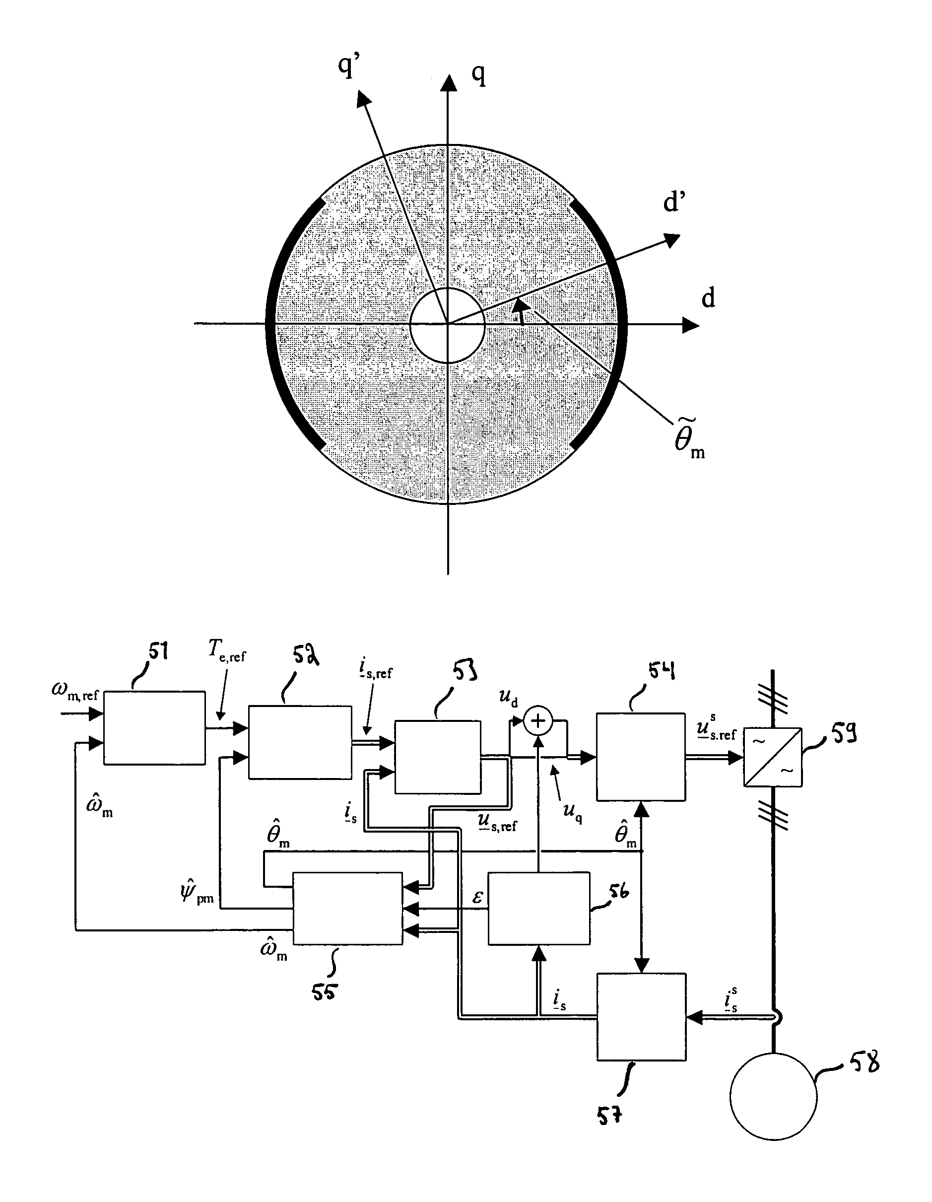
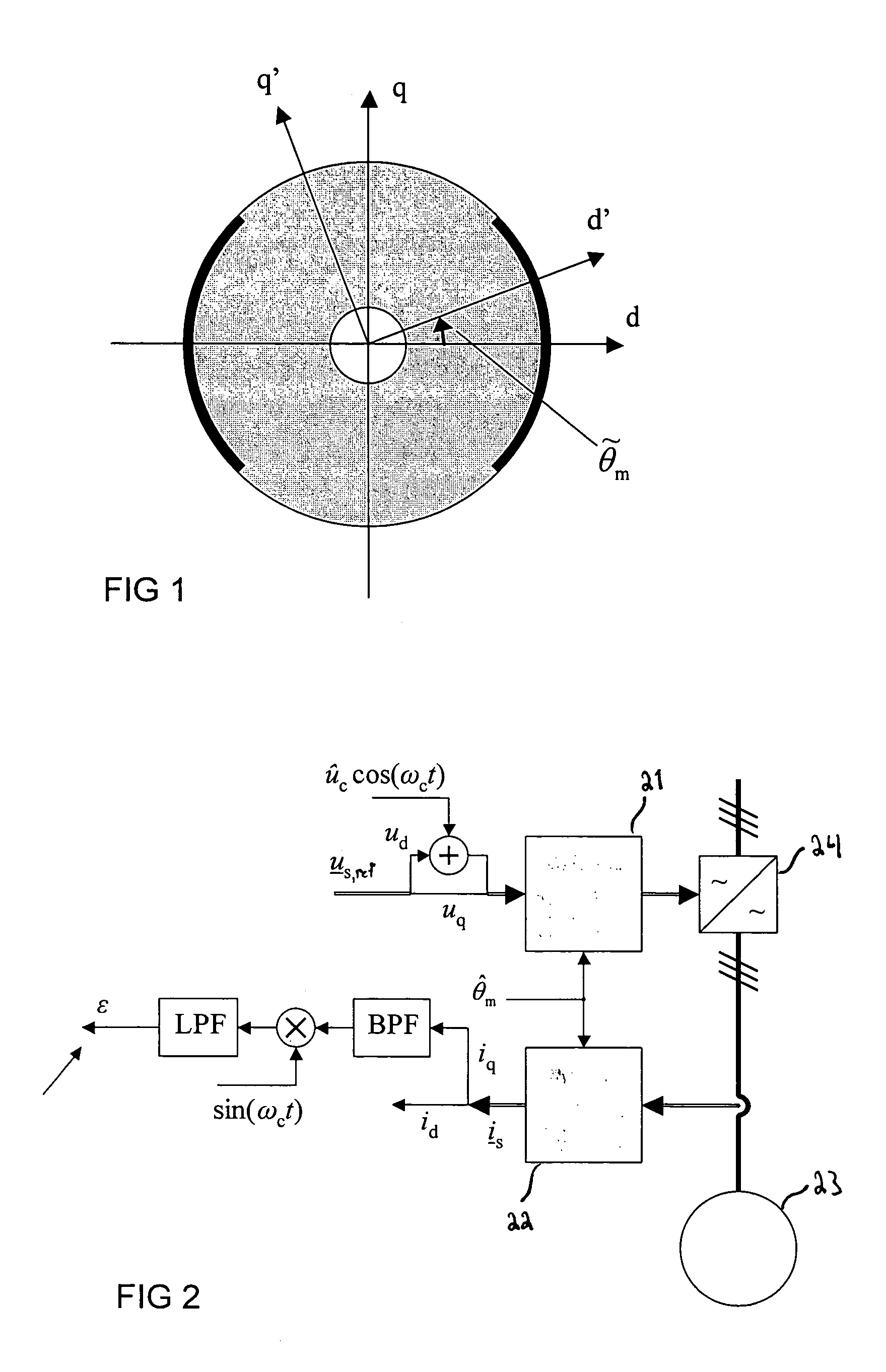
[0015]In the following, there is first described in detail a voltage model known per se, then signal injection known per se and finally a combination of these two, which constitutes a method of the invention.

Voltage Model

[0016]As mentioned above, in a flux observer based on a voltage model the flux and the speed are estimated from a stator voltage and a measured stator current. The voltage model is based on a motor voltage equation, which in connection with a solid rotor synchronous machine is expressed as

[0017]u_ss=Rs⁢i_ss+Ls⁢ⅆⅆt⁢i_ss+ⅆⅆt⁢ψ_pms(1)

where uss is stator voltage in stator coordinates, is iss a stator current, Ls is stator inductance, Rs is stator resistance and ψpms is a permanent magnet flux vector in stator coordinates. A time derivative estimate of the permanent magnet flux, i.e. a time derivative calculated from the estimated quantities, in the stator coordinates, is written as

[0018]e^_fs=ⅆⅆt⁢ψ^_pms(2)

where a circumflex above a quantity denotes an estimate of the qu...


PUM

PropertyMeasurementUnit
frequencyaaaaaaaaaa
speedaaaaaaaaaa
voltageaaaaaaaaaa

Abstract

A method for determining the speed and position of a rotor of a salient-pole permanent magnet synchronous machine, the method comprising the steps of creating a voltage model (41) on a permanent magnet synchronous machine, forming a voltage reference (us,ref) for a stator of the permanent magnet synchronous machine, determining stator currents (is) of the permanent magnet synchronous machine, calculating a rotor angular speed (42) from the voltage reference (us,ref) and the stator currents (is) using the voltage model (41). The method further comprises the steps of forming with signal injection a position tracking signal (ε) of the rotor of the permanent magnet synchronous machine, forming a rotor angular speed estimate ({circumflex over (ω)}m) from the calculated rotor angular speed (42) and the rotor position tracking signal (ε), forming a rotor position angle estimate ({circumflex over (θ)}m) from the formed rotor angular speed estimate ({circumflex over (ω)}m) and the rotor position tracking signal (ε).

Description

BACKGROUND OF THE INVENTION[0001]The present invention relates to a method in connection with a salient-pole permanent magnet synchronous machine in accordance with the preamble of claim 1.[0002]For reliable operation a plurality of motor control systems require accurate information on a position angle and angular speed of a rotor. In a typical implementation the position angle and the angular speed of the rotor are determined using a mechanical sensor coupled on a motor shaft. This sensor produces information, for instance, on the rotor position and from a change in the position it is further possible to calculate the angular speed of the rotor. However, the sensor coupled to the shaft is a mechanical component liable to faults, which increases the price of a motor drive considerably. In addition, as the motor drive control is based on information obtained from the sensor, sensor breakage inevitably causes downtime in said motor drive.[0003]There are also currently used a variety o...

Claims


Application Information

Patent Timeline
Patent Type & Authority Patents(United States)
IPC IPC(8): G01B7/30G01P3/46H01F5/00H02P21/14H02P25/02
CPCH02P21/0046H02P21/146H02P2203/05H02P2203/11H02P2207/05H02P21/28H02P21/18
Inventor PIIPPO, ANTTI
Owner ABB OY
Why Eureka
Try Eureka