
Method for minimizing the error of a measurable quantity

Inactive Publication Date: 2007-05-22
CS CLEAN SYST AG
View PDF11 Cites 3 Cited by
  • Summary
  • Abstract
  • Description
  • Claims
  • Application Information

AI Technical Summary

Benefits of technology

[0008]The present invention is based on the object of specifying a method for minimizing the error of a measured variables particularly a signal to be measured, which avoids the disadvantages of the related art. In particular, a signal output which is optimum in regard to the noise and the response time is to be ensured.
[0009]According to the invention, a method for minimizing the error of a measured variable, particularly a signal to be measured using filtering at variable bandwidth, is proposed, in which signal changes not caused by noise, i.e., changes of the information component of the signal, are recognized as early as possible, the bandwidth being regulated on the basis of a physical criterion inherent to the method.
[0014]Through the method according to the present invention, it is ensured that a signal change not caused by noise, i.e., a variation of the information component, is recognized as early as possible, since the next lower filter has a variation in the measured signal which is greater than the intrinsic noise, so that there must be a signal change not caused by noise. In addition, the signal change may not be recognized earlier, since all filters of higher bandwidth have variations so large that they cover the information component of the signal. The earliest-possible recognition of the change in the information component of the signal, which is achievable according to the present invention, is an important advantage in thermal radiation detectors or further safety-relevant applications, for example. Furthermore, the method presented here has the advantage that the bandwidth regulation is based on a physical criterion.
[0017]The method presented here is free of feedback and offers stability based on a principle.

Problems solved by technology

In this case, a data rate reduction may occur, which saves significant computing time and storage space.

Method used


Image

  • Method for minimizing the error of a measurable quantity
  • Method for minimizing the error of a measurable quantity
  • Method for minimizing the error of a measurable quantity

Examples


Embodiment Construction

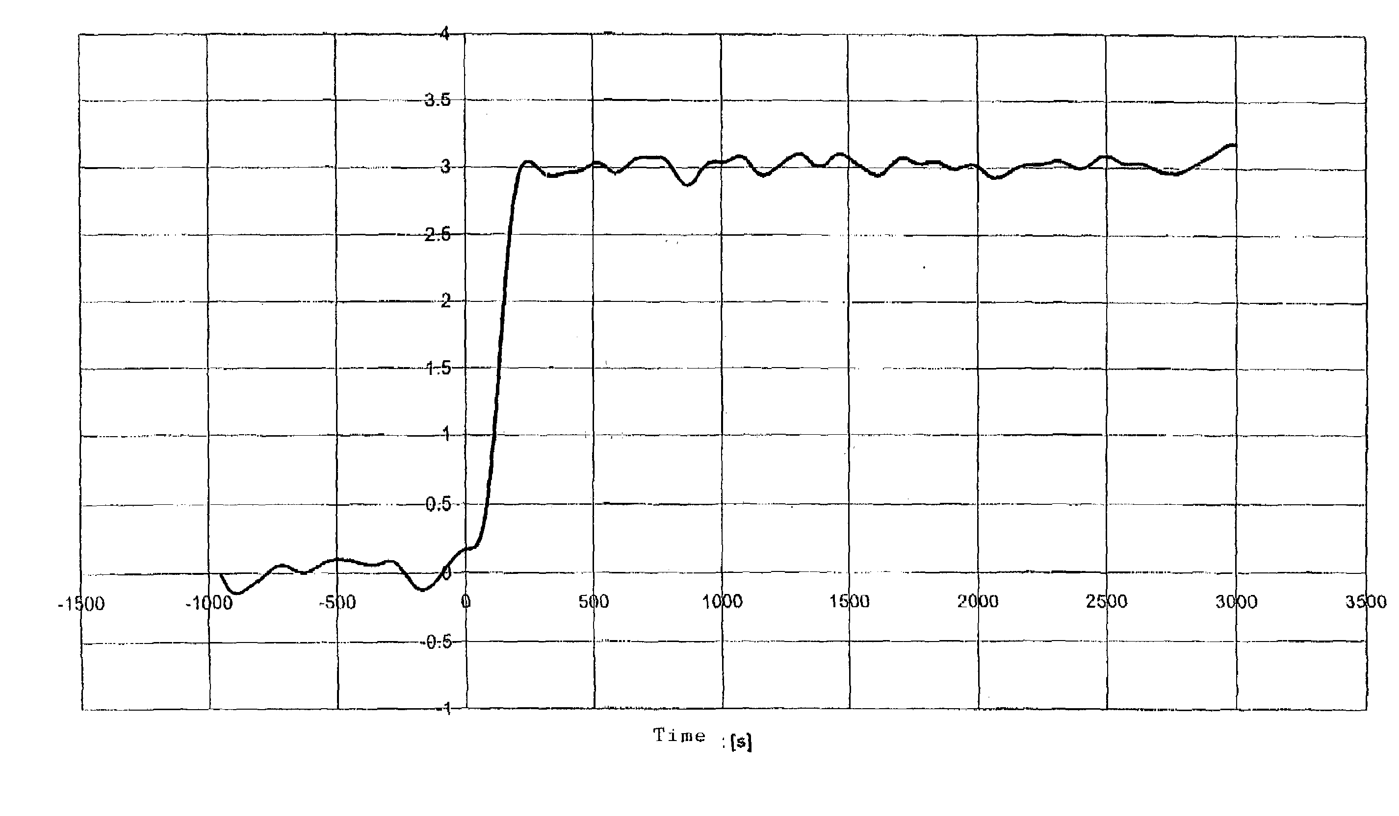
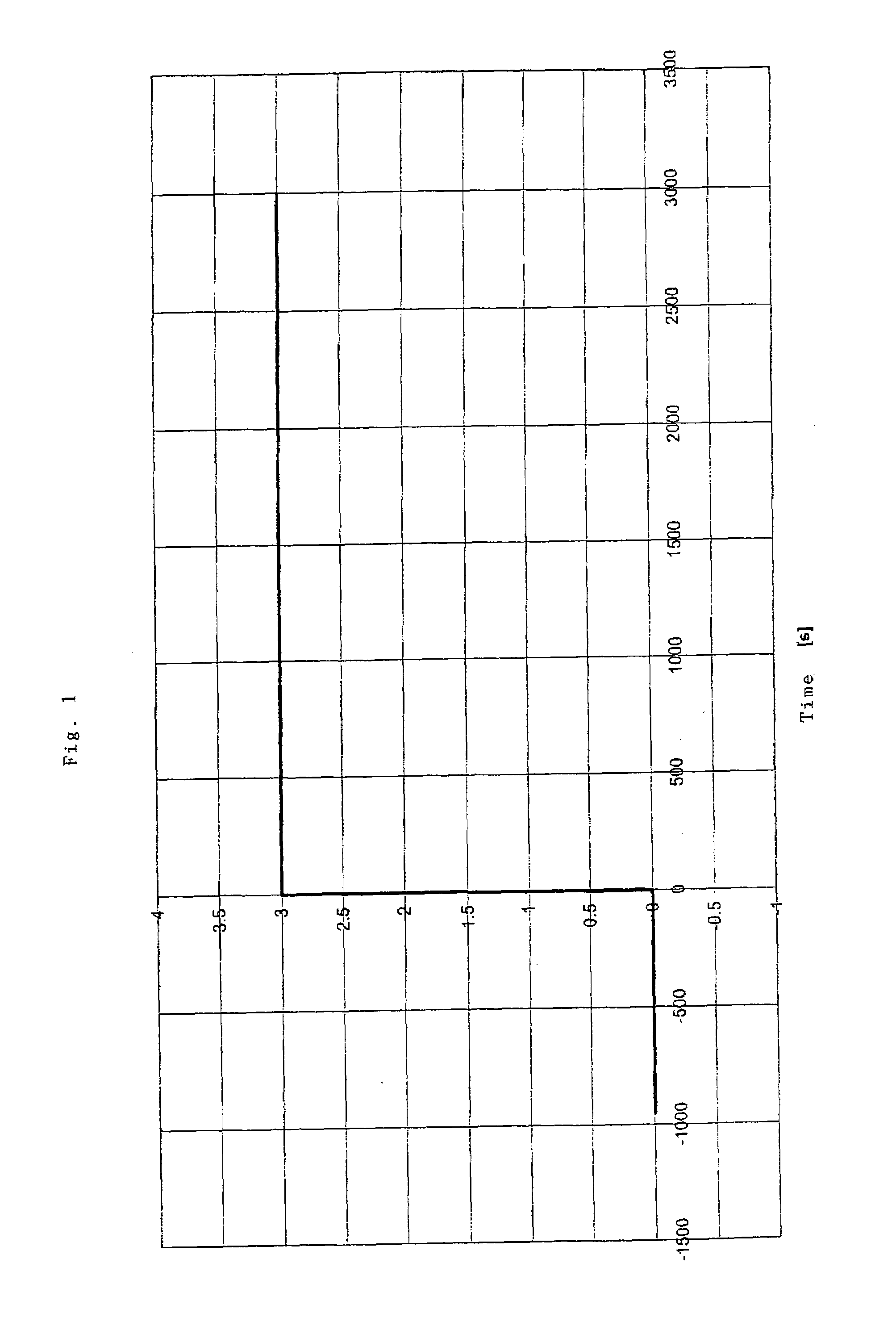
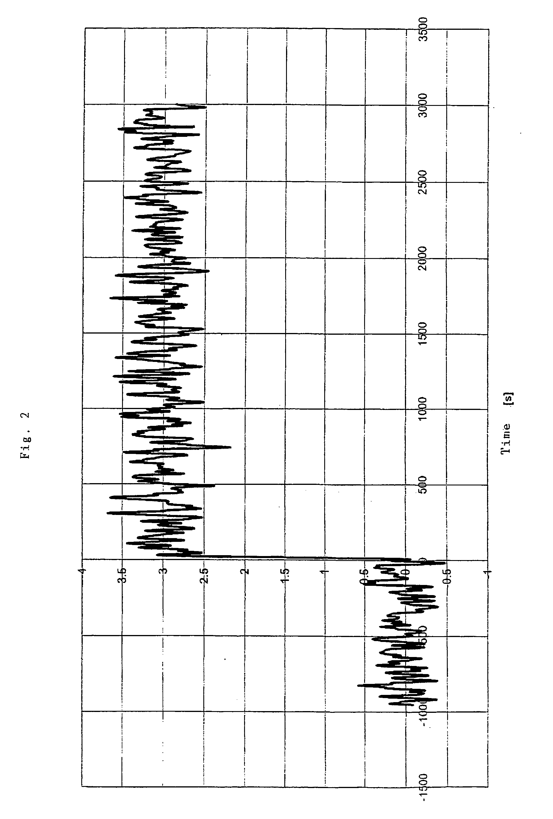
[0036]The preferred embodiment of the present invention will now be described with reference to FIGS. 1–9 of the drawings. Identical elements in the two figures are designated with the same reference numerals.

[0037]A multiple of the standard deviation σ of the intrinsic noise of the measuring sensor is used as the threshold value for the absolute value of the distance of the observed filter output to a filter output of lower bandwidth, because of which the signal analysis is based on a physical criterion inherent in the measurement system. This avoids a filter being sought out on the basis of arbitrary parameters and / or parameters generated outside the measurement system and thus being displayed. If the distance between the observed filter output and a filter output of lower bandwidth is within the setpoint interval, then this distance corresponds to the random noise of the observed filter output.

[0038]An exemplary decision procedure of this type is illustrated in FIG. 7. Curve A sh...


PUM


Abstract

In the framework of the method for minimizing the error of a measured variable, particularly a signal to be measured using filtering at variable bandwidth, the bandwidth is regulated on the basis of a physical criterion inherent to the method in such a ways that signal changes not caused by noise are recognized as early as possible.

Description

BACKGROUND OF THE INVENTION[0001]The present invention relates to a method for minimizing the error of a measured variable.[0002]Typically, measured signals have a noise component in addition to the information component. The noise amplitude and / or the noise component of the measured signal is typically reduced through low-pass filtering at the cost of the response time.[0003]For this reason, it is generally necessary to find a compromise between lower noise amplitude and shorter response time when evaluating a measured signal.[0004]According to the related art, filters having a fixed high bandwidth, which have a short response time, are often used; filters of this type have a high noise amplitude, however. However, by using filters having a fixed low bandwidth, the noise amplitude may be reduced, but, as already noted, this procedure results in a longer response time.[0005]Therefore, if a low noise amplitude Is desired in addition to a short response time, a filter having fixed ban...

Claims


Application Information

Patent Timeline
IPC IPC(8): H04B15/00G01D3/032
CPCG01D3/032
Inventor WIECHERS, JOACHIM
Owner CS CLEAN SYST AG
Learn More