Aircraft ram air inlet with multi-member closure flap

a technology air intake, which is applied in the direction of air-treatment apparatus arrangement, aircraft power plants, weight reduction, etc., can solve the problems of unoptimized prior location of ram air inlet, achieve efficient control of ram airflow, reduce the disruption of the optimized aerodynamic contour of the leading edge, and increase the overall air resistance

Inactive Publication Date: 2007-05-29
AIRBUS OPERATIONS GMBH
View PDF43 Cites 39 Cited by
  • Summary
  • Abstract
  • Description
  • Claims
  • Application Information

AI Technical Summary

Benefits of technology

[0012]Further preferably according to the invention, the front flap is outwardly convexly curved with a curvature matching the contour curvature of the sectional profile of the leading edge of the wing, while the rear flap is substantially flat or planar. With this arrangement, the front flap can be actuated to close the air intake opening, while providing a substantially flush and uninterrupted outer aerodynamic contour of the leading edge of the wing. This achieves a low disruption of the optimized aerodynamic contour of the leading edge of the wing, and thus does not produce any significant increase of the overall air resistance, and does not cause any significant airflow disturbance, separation, or turbulence of the incident...

Problems solved by technology

Especially with such a location of the air conditioning packs, the previously existing locatio...

Method used


Image

  • Aircraft ram air inlet with multi-member closure flap
  • Aircraft ram air inlet with multi-member closure flap
  • Aircraft ram air inlet with multi-member closure flap

Examples


Embodiment Construction

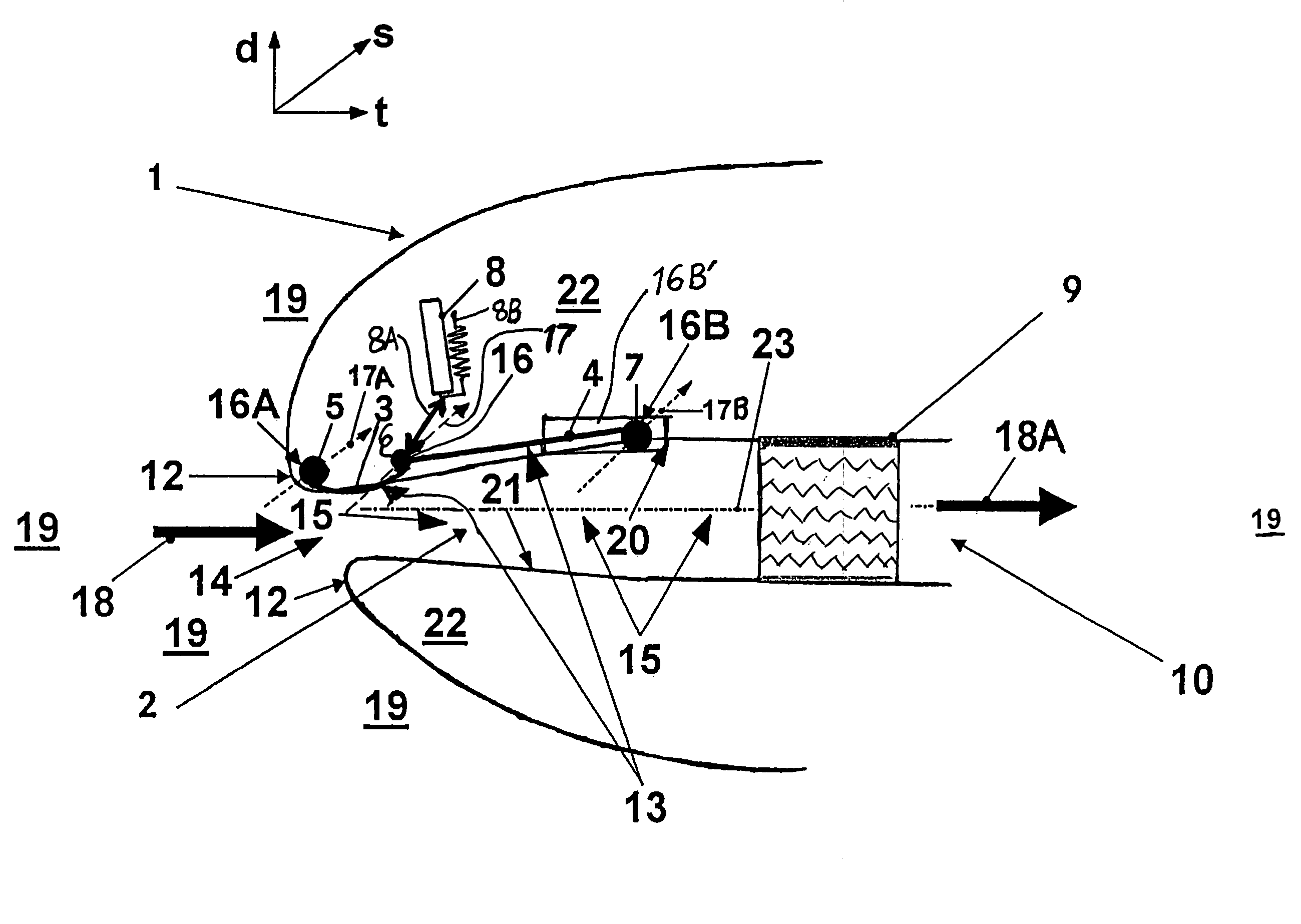
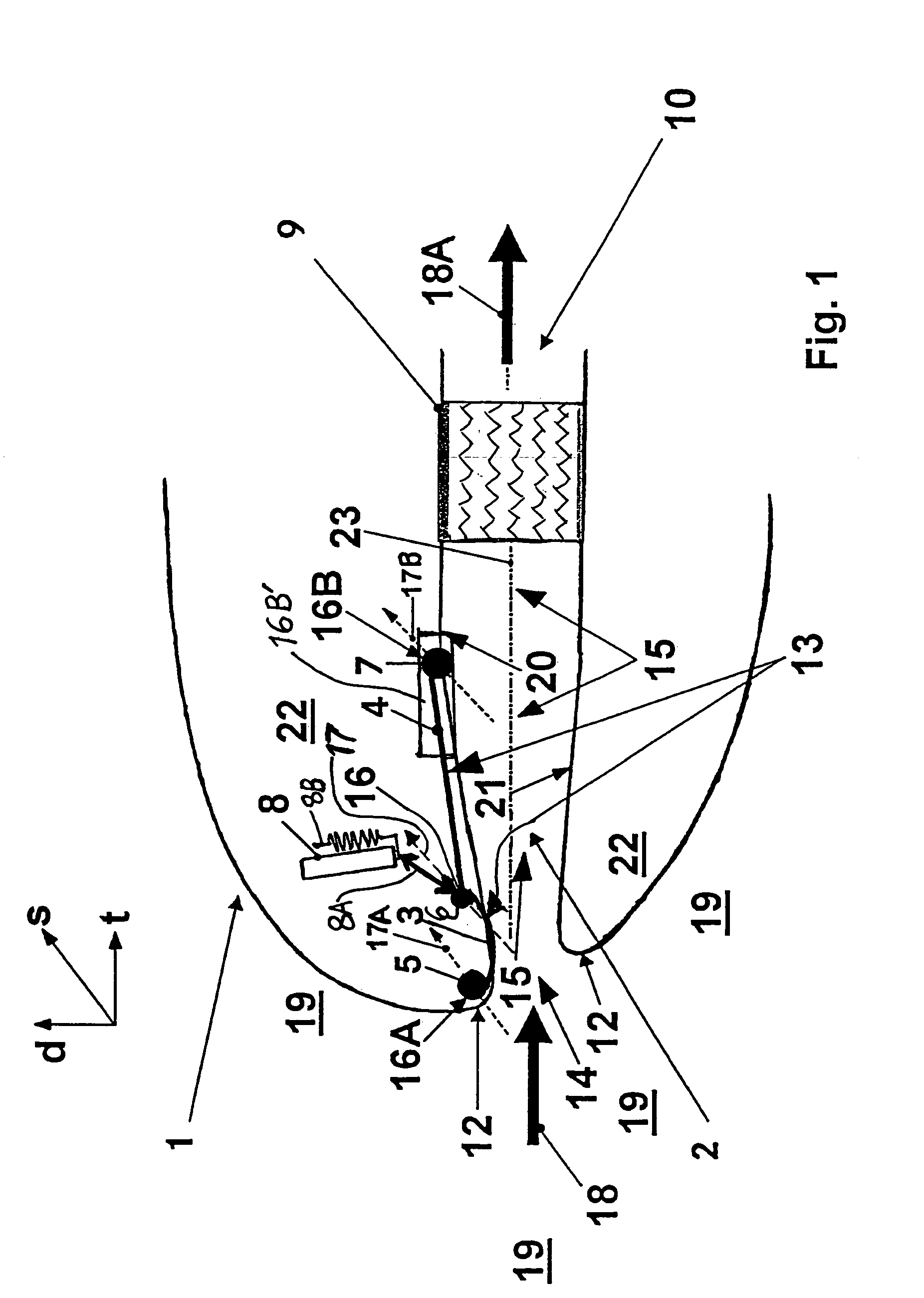
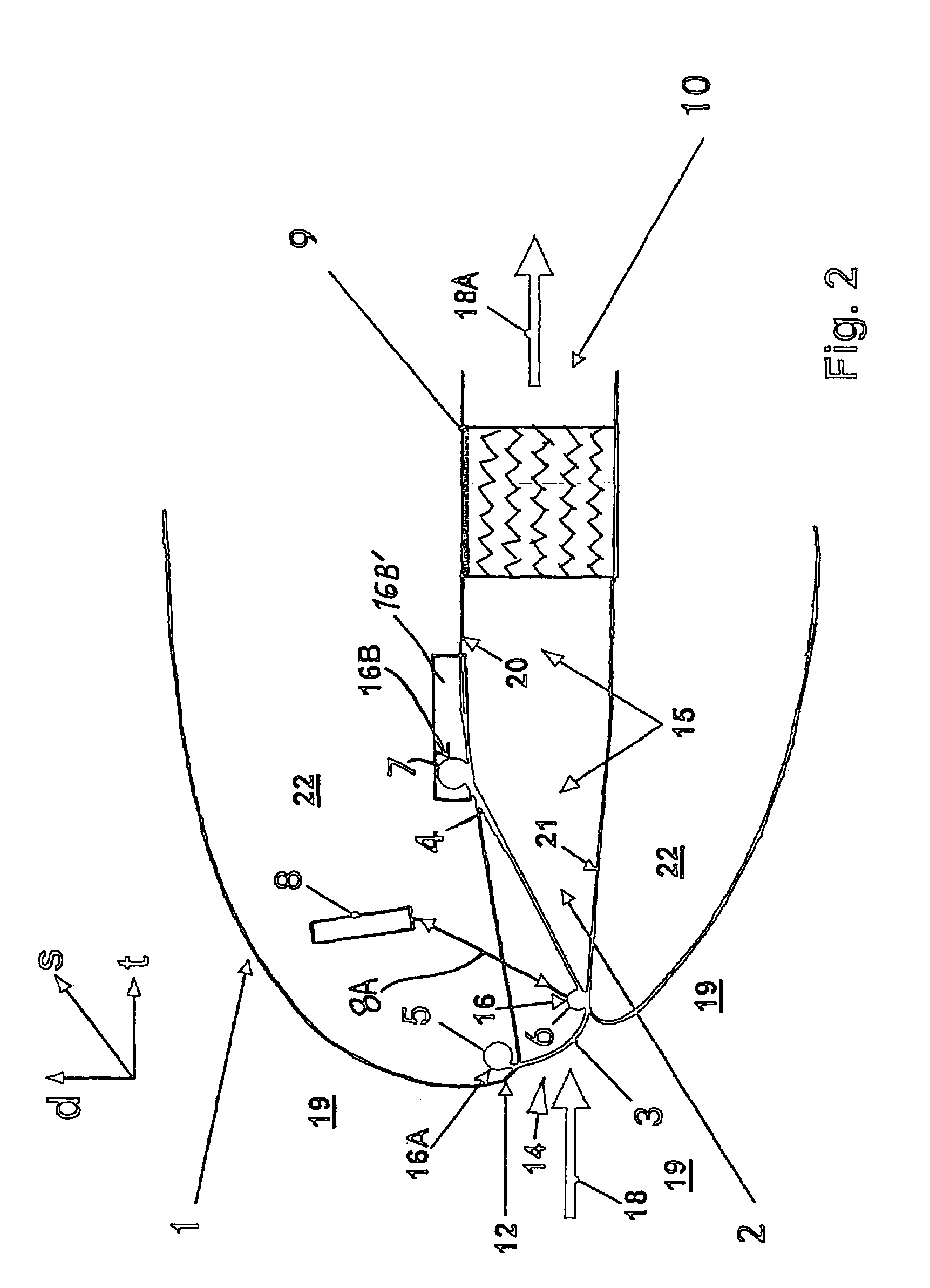
[0020]The drawings schematically illustrate several example embodiments of a ram air inlet or intake arrangement according to the invention, of which the air intake opening 14 is let into the outer contour of the leading edge 12 of a lifting wing 1 of an aircraft. This location is selected because the incident airflow of ambient air 19 surrounding the wing 1 forming a ram airflow 18 will develop the maximum stagnation or ram air pressure along the curved nose of the leading edge 12 of the lifting wing 1 during flight of the aircraft. Thus, the selected location of the air intake opening 14 is preferably the optimum ram or stagnation point on the wing leading edge 12. By moving the ram air intake opening from the conventional location in the belly fairing to the leading edge of the wing, this frees additional space in the belly fairing for other systems. The flap arrangement as described in detail below is very simple, and the length of the ram air channel 2 can be reduced to a minim...


PUM


Abstract

A ram air inlet includes a channel with an intake in a wing leading edge, front and rear flaps arranged in the channel for selectively closing or opening the channel, and an actuator connected to the flaps. A front end of the front flap is pivotably connected by a fixed bearing to an aircraft structure adjacent the intake. A rear end of the rear flap is moveably and pivotably mounted to the aircraft structure via a movable bearing arrangement, e.g. a pivot bearing linearly movable in guide tracks, or a flexible lever connected to a fixed pivot bearing, or a swinging bearing pivotably connected to a fixed bearing. The opposite ends of the flaps are pivotably connected to each other by a third bearing. The actuator drives the third bearing to pivot the front flap between opened and closed positions, while the rear flap pivots and moves in the wing chord and/or thickness directions.

Description

PRIORITY CLAIM[0001]This application is based on and claims the priority under 35 U.S.C. §119 of German Patent Application 103 35 482.4, filed on Aug. 2, 2003, the entire disclosure of which is incorporated herein by reference.FIELD OF THE INVENTION[0002]The invention relates to a ram air inlet or intake arrangement of an aircraft, including a ram air channel with an intake opening, and a flap arrangement to selectively open or close the air intake opening.BACKGROUND INFORMATION[0003]Conventional passenger transport aircraft typically include an air conditioning system including one or more air conditioning plants or packs, commonly based on an air cycle process, in which highly compressed process air, namely bleed air from a propulsion engine or an auxiliary power unit (APU) engine, is compressed and expanded, while being cooled by heat exchange at one or more stages. Through this air cycle, the process air is cooled and dehumidified. The cooling of the process air through a heat e...

Claims


Application Information

Patent Timeline
IPC IPC(8): B64D33/02B64D13/00
CPCB64D13/00Y02T50/44Y02T50/40
Inventor KELNHOFER, JUERGEN
Owner AIRBUS OPERATIONS GMBH
Why Eureka
Try Eureka