Signal processing circuit and liquid crystal display device using the same

a liquid crystal display device and processing circuit technology, applied in the field of signal processing circuits, can solve the problems of image quality degradation, difficult to provide low power consumption for a normal display without reducing the number of displayable colors and image quality, and achieve the effect of reducing power consumption levels

Inactive Publication Date: 2007-05-29
ALPS ALPINE CO LTD
View PDF3 Cites 13 Cited by
  • Summary
  • Abstract
  • Description
  • Claims
  • Application Information

AI Technical Summary

Benefits of technology

[0034]Because of the aforementioned advantages of the driving voltage generation circuit, the liquid crystal drivi

Problems solved by technology

However, this structure allows for only chip-based batch control of the output modes of the source driver because of standby-mode control.
Thus, only eight colors are represented by using one-bit (the most significant bit) grayscale data for each of R (red), G (green), and B (blue); whereas, 260,000 colors are represe

Method used


Image

  • Signal processing circuit and liquid crystal display device using the same
  • Signal processing circuit and liquid crystal display device using the same
  • Signal processing circuit and liquid crystal display device using the same

Examples


first embodiment

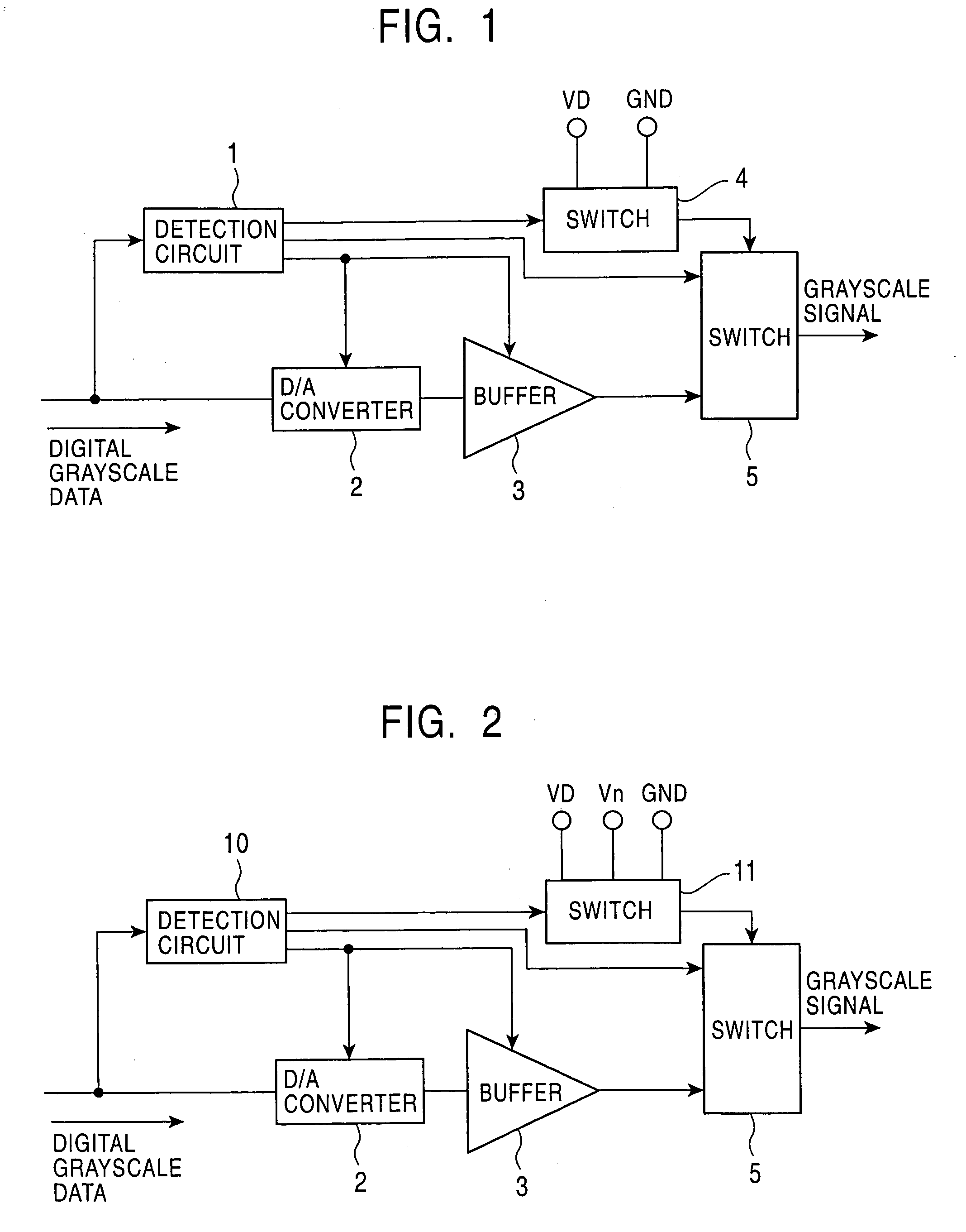
[0042]FIG. 1 is a concept diagram of a driving voltage generation circuit according to a first embodiment of the present invention.

[0043]A source driver according to embodiments of the present invention is similar to the source driver 200 used in the liquid crystal display device shown in FIG. 5 having the structure shown in FIG. 4, whereas a driving voltage generation circuit 150 has the structure shown in FIG. 1.

[0044]The driving voltage generation circuit shown in FIG. 1 includes at least a detection circuit 1, a D / A converter 2, a buffer 3, and switches 4 and 5.

[0045]The detection circuit 1 determines whether or not digital grayscale data input from a latch (not shown), e.g., the latch 103 shown in FIG. 4, matches internal set data that is set in advance.

[0046]Assuming that digital grayscale data to be converted into an analog grayscale voltage is 6-bit data, the set data is, for example, digital grayscale data indicating gray levels 63 and 0, which require higher power consumpt...

second embodiment

[0073]FIG. 2 is a concept diagram of a driving voltage generation circuit according to a second embodiment of the present invention.

[0074]In the driving voltage generation circuit shown in FIG. 2, similar elements to those shown in FIG. 1 are given the same reference numerals, and a description thereof is omitted.

[0075]The difference from the driving voltage generation circuit of the first embodiment is that a switch 11 further receives an intermediate voltage Vn similar to an analog grayscale voltage corresponding to, for example, a frequently used gray level, in addition to the predetermined voltages input to the switch 4 shown in FIG. 1, i.e., the power supply voltage VD and the ground voltage GND.

[0076]In accordance with the structure of the switch 11, the digital grayscale data corresponding to the power supply voltage VD, the ground voltage GND, and the intermediate voltage Vn, represented by “3F”, “00”, and “NN (any gray level value)”, respectively, are set as the set data of...

third embodiment

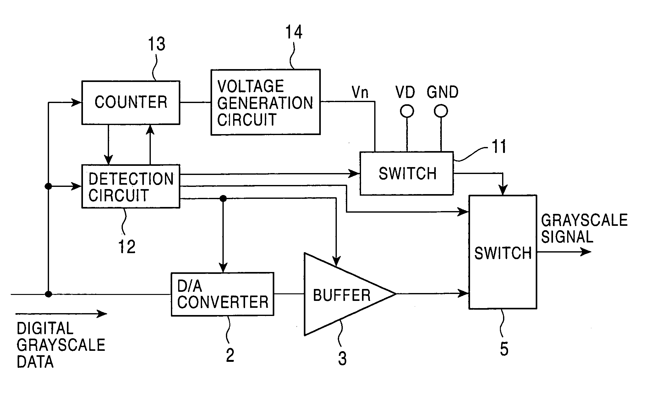
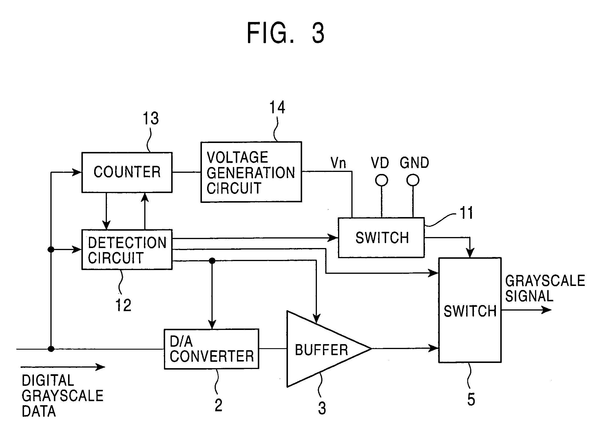
[0081]FIG. 3 is a concept diagram of a driving voltage generation circuit according to a third embodiment of the present invention.

[0082]In the driving voltage generation circuit shown in FIG. 3, similar elements to those shown in FIG. 2 are given the same reference numerals, and a description thereof is omitted.

[0083]The difference from the driving voltage generation circuit of the second embodiment is that the driving voltage generation circuit of the third embodiment shown in FIG. 3 further includes a power supply generation circuit 14 for generating an intermediate voltage equivalent to an analog grayscale voltage corresponding to a frequently used gray level to be supplied to the switch 11.

[0084]The driving voltage generation circuit of the third embodiment further includes a counter 13. Each time a pixel is input, the counter 13 counts each of the gray levels to be used in the input pixel, for example, 64 gray levels that ranges from “63” to “00”, and outputs the gray level ha...


PUM


Abstract

A signal processing circuit includes a digital-to-analog (D/A) conversion circuit having a D/A converter and a buffer for converting input digital grayscale data into an analog voltage and outputting the converted analog voltage, a first switch that changes its output mode so that a supplied voltage is output as a supply analog voltage, a second switch that outputs any of the converted analog voltage and the supply analog voltage as an analog voltage, and a detection circuit. The detection circuit determines whether or not the input digital grayscale data matches internal set data. When it is determined that the input digital grayscale data matches the set data, the detection circuit switches the first switch so that the supply analog voltage corresponding to the digital grayscale data is output, and also switches the second switch so that the supply analog voltage is output.

Description

BACKGROUND OF THE INVENTION[0001]1. Field of the Invention[0002]The present invention relates to a signal processing circuit, and particularly to a circuit that drives a liquid crystal device in a liquid crystal display device.[0003]2. Description of the Related Art[0004]As shown in FIG. 4, a liquid crystal driving circuit is formed comprising a digital circuit and an analog circuit.[0005]The digital circuit includes a shift register 101 to which data is input column-by-column, data registers 102 that receive data to be displayed from the shift register 101 and that temporarily store the received data, and data latches 103 that hold the data which is being displayed.[0006]The analog circuit includes D / A (digital-to-analog) converters 104 that convert digital data to analog data based on a predetermined relationship, and buffers 105 for power amplification of the converted analog data to drive liquid crystal devices.[0007]A liquid crystal display device has the structure shown in FIG...

Claims


Application Information

Patent Timeline
IPC IPC(8): G09G3/36G02F1/133G09G3/20H03M1/66H04N5/66
CPCG09G3/2011G09G3/3688G09G2330/021G09G2310/027A61G13/121A61G13/122A61H37/00A61G2200/325A61H2201/1607A61H2201/1621
Inventor YAMADA, YUKIMITSU
Owner ALPS ALPINE CO LTD
Why Eureka
Try Eureka