
Method and apparatus for precisely fitting, reproducing, and creating 3-dimensional objects from digitized and/or parametric data inputs using computer aided design and manufacturing technology

a technology of applied in the field of methods and equipment for precisely fitting, reproducing, and creating 3dimensional objects from digitized and/or parametric data inputs using computer aided design and manufacturing technology, to achieve the effect of maximizing cutter efficiency, facilitating easy import of geometry and automatic calculation of toolpaths

Inactive Publication Date: 2007-05-29
SUTULA JR DANIEL P
View PDF13 Cites 46 Cited by
  • Summary
  • Abstract
  • Description
  • Claims
  • Application Information

AI Technical Summary

Benefits of technology

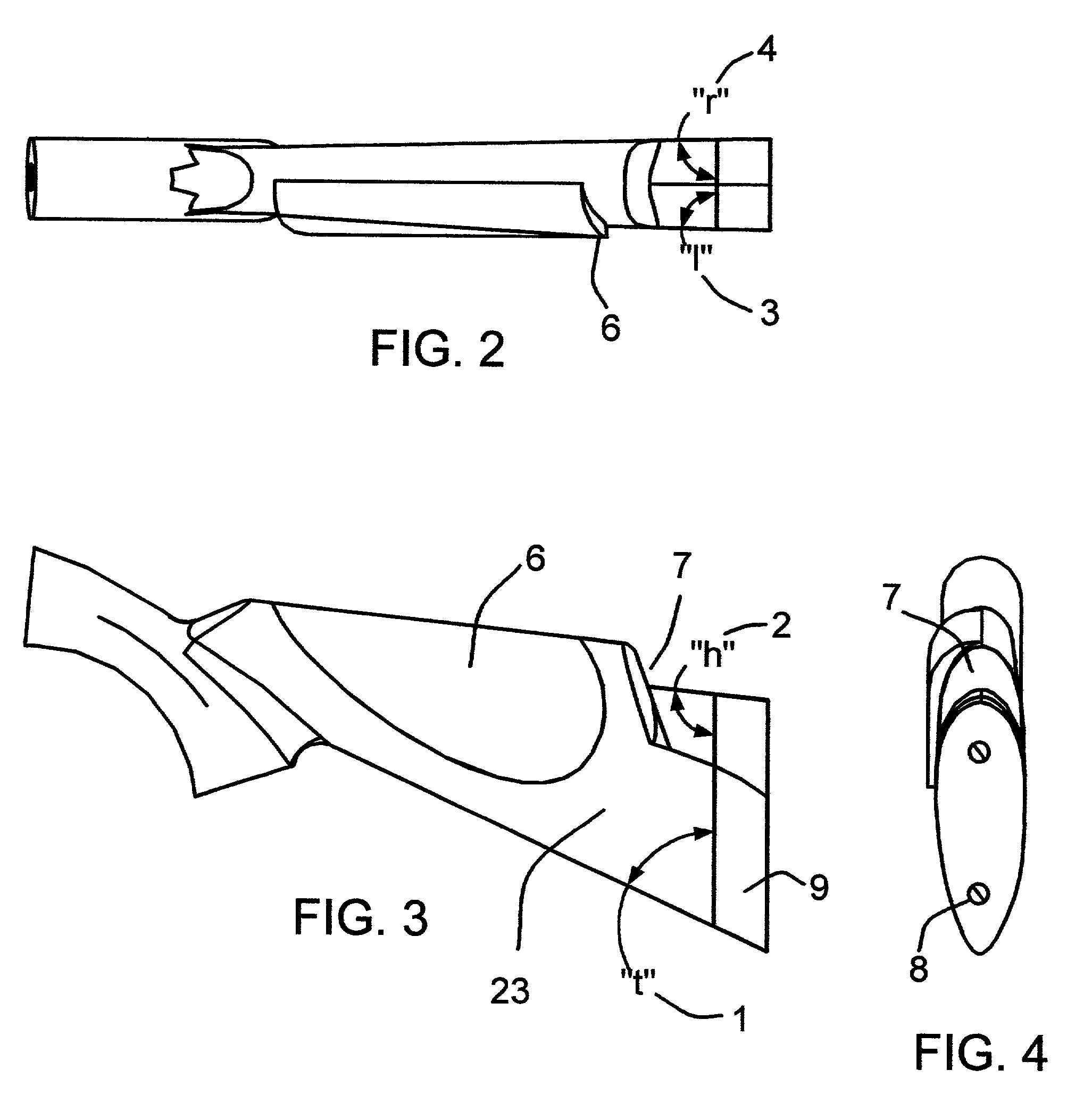
"The patent describes a method for accurately fitting a recoil pad to a gun or sighting ribs. The method involves accurately measuring the profile of the stock and the options specified by the customer. A novel instruction and data acquisition form is used to collect all required measurements. The profile of the perimeter of the gunstock is accurately traced and recorded using a fine point stylus. The angle of the surface along the profile is also considered to properly fit the recoil pad. The invention provides a disposable angle gage, comparator, or protractor type device for measuring angles without scratching the gun. The traced profile data can be scanned or digitized using optical scanners and converted into a computerized model for further use. The resulting 3-D surface is representative of the side surfaces of the recoil pad."

Problems solved by technology

While angle gages or protractors are the traditional tools used for measuring angles, many prospective customers are not likely own one of these specialized tools.
Moreover, most angle gages are made of metal that could scratch a gunstock accidentally.

Method used


Image

  • Method and apparatus for precisely fitting, reproducing, and creating 3-dimensional objects from digitized and/or parametric data inputs using computer aided design and manufacturing technology
  • Method and apparatus for precisely fitting, reproducing, and creating 3-dimensional objects from digitized and/or parametric data inputs using computer aided design and manufacturing technology
  • Method and apparatus for precisely fitting, reproducing, and creating 3-dimensional objects from digitized and/or parametric data inputs using computer aided design and manufacturing technology

Examples


Embodiment Construction

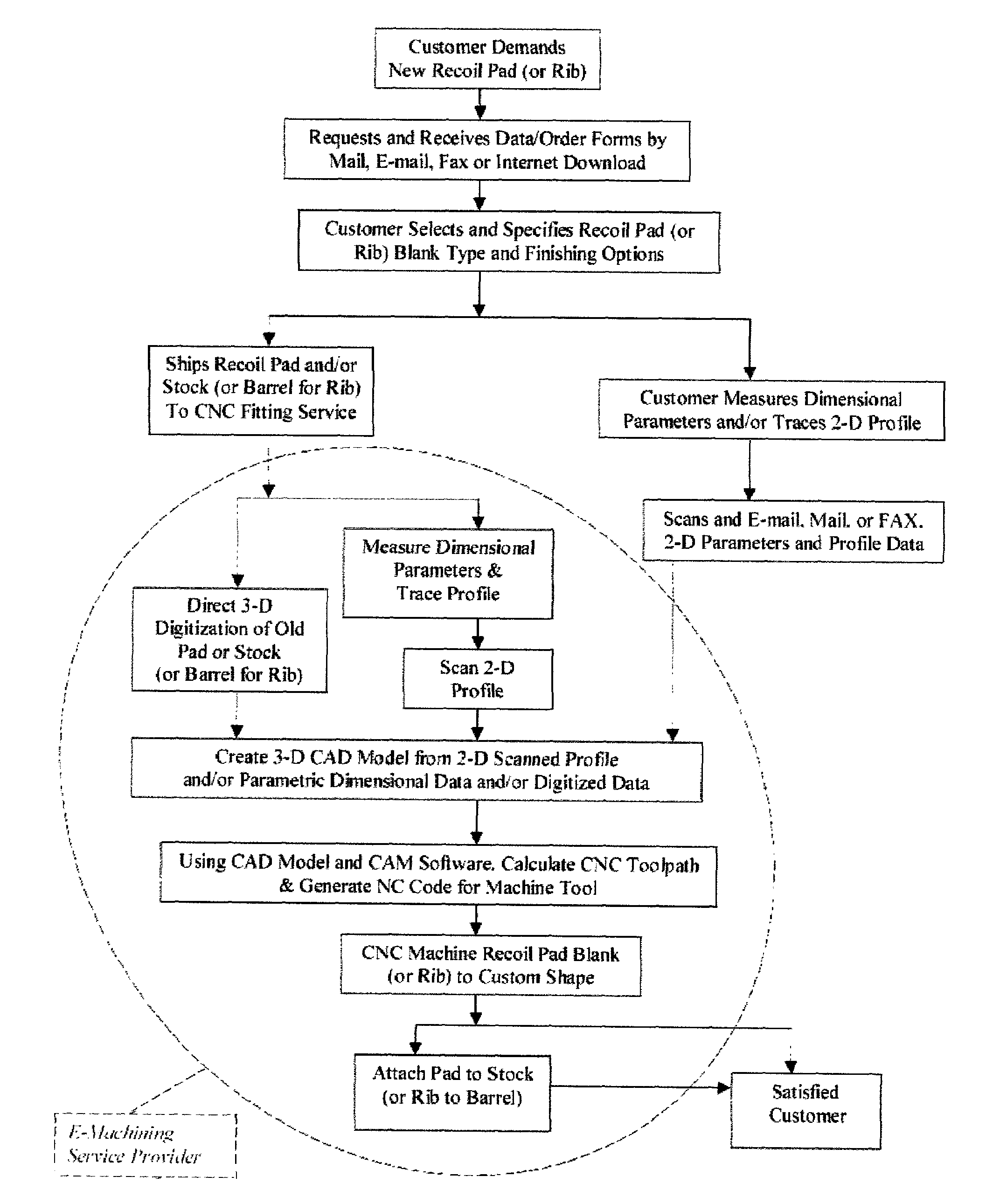
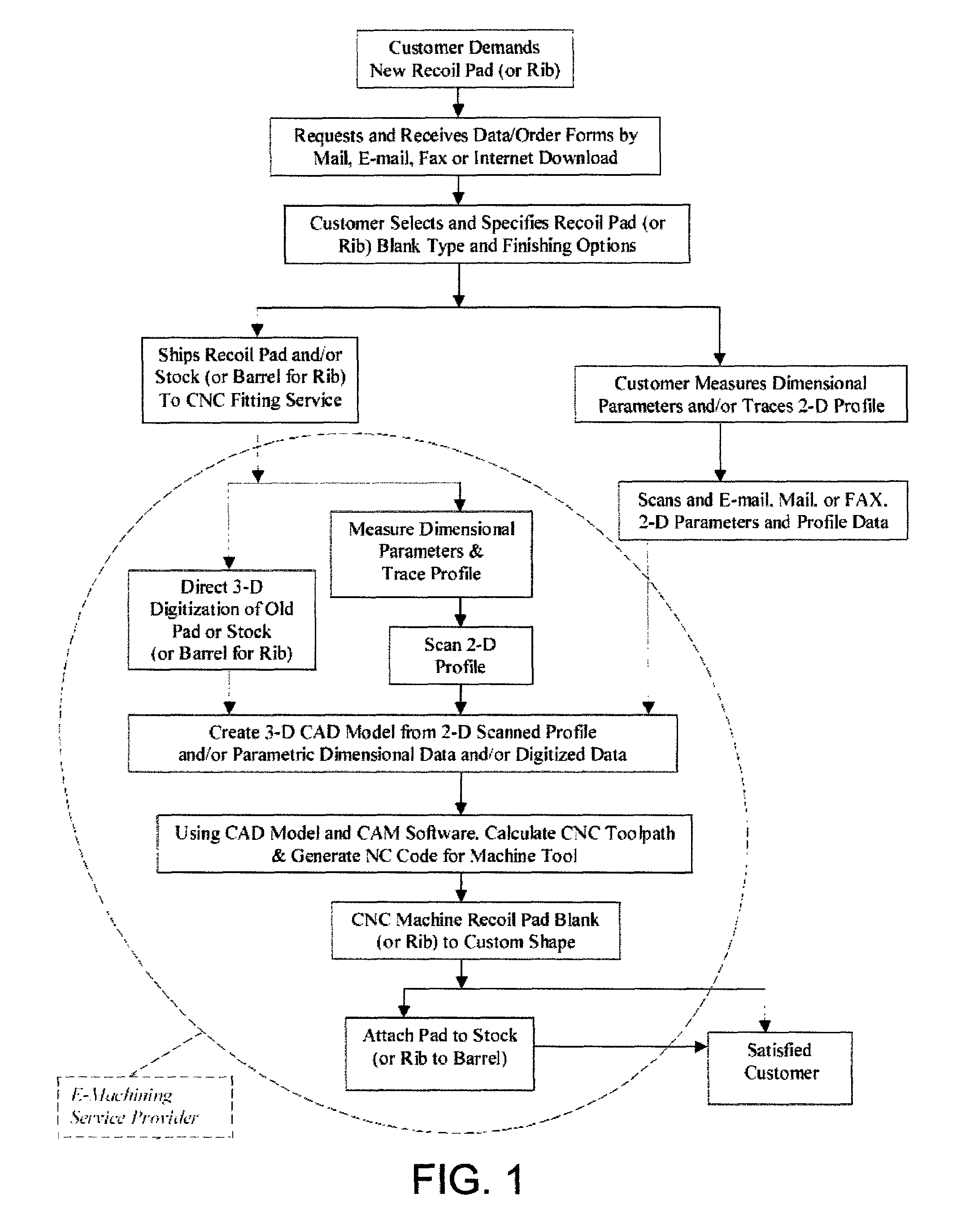
[0050]FIG. 1 shows a flow chart outlining combinations of steps, which comprise the method of this invention. The flow chart starts with the customer who needs or wants a new recoil pad. The customer may request the appropriated data and order forms from the e-machining service provider either by mail, phone, fax, or e-mail. The customer may also download the forms directly from the ESP's internet web site. The customer must then select the type or style recoil pad they desire, along with their preferences with regard to the final size and surface finish. For example some may prefer a slightly oversized or undersized pad instead of an exact fitting pad. The customer must then decide whether they are going to take the measurements themselves or leave this task to the ESP. If the customer elects to take measurements themselves, they must transmit the data to the ESP by mail, fax, or by e-mailing the data along with a scanned image of the butt profile. Alternately, the customer may ele...


PUM


Abstract

A high-technology method for creating, reproducing, and or precisely fitting custom appendages to topographically complex structures. The method comprises a combination of novel measurement techniques in conjunction with computerized modeling and machining processes applied to achieve a virtually perfect tailored fit with mating structures. The method does not require the physical presence of the mating structure so the modeling and machining operations may be conducted at a separate location based solely on parametric dimensional and / or graphical data inputs and a customized data form. Said data may be transmitted conventionally or electronically as by fax or the internet. The invention includes a printed virtual protractor tool (16) for accurately measuring angles. A means for direct digitization of the required topological data input is also provided. The novel aspects of this invention can be combined with conventional fitting equipment and processes. The scope of this invention is exceedingly broad with a variety of potential applications cited. Two examples are presented to illustrate utility in the context of complex operations routinely encounter by gunsmiths in fitting recoil pads (9) to gunstocks (23) and fitting sighting ribs (37) to gun barrels (42).

Description

BACKGROUND OF THE INVENTION[0001]1. Field of the Invention[0002]The present invention relates to a novel high-technology method enabling precision creation and / or fitting of custom appendages to topographically complex two-dimensional and three-dimensional structures. The method comprises a combination of computerized tools and techniques employed to produce a virtually perfect fit with mating structures. The fitting method does not require the physical presence of the mating structure, and may be accomplished using only parametric dimensional and / or graphical data inputs that may be transmitted conventionally or electronically. If the mating structure is available, the method provides a means for direct digitization of the required topological data input. Novel elements of this method may also be used in conjunction with conventional fitting equipment and processes. The methods of this invention apply broadly to the general field of custom fitting appendages of all types. Two examp...

Claims


Application Information

Patent Timeline
Patent Type & Authority Patents(United States)
IPC IPC(8): G06F19/00G05B19/4099G05B19/42
CPCG05B19/4099G05B19/4207G05B2219/49008Y02P90/02
Inventor SUTULA, JR., DANIEL P.
Owner SUTULA JR DANIEL P
Learn More