
Wireless communication for diagnostic instrument

a diagnostic instrument and wireless communication technology, applied in the field of diagnostic instruments, can solve the problems of consuming consuming unnecessary diagnostic or repair time, and compromising the portability of handheld computing devices, and achieve the effect of facilitating collaborative work

Inactive Publication Date: 2007-05-29
SNAP ON INC +1
View PDF10 Cites 9 Cited by
  • Summary
  • Abstract
  • Description
  • Claims
  • Application Information

AI Technical Summary

Benefits of technology

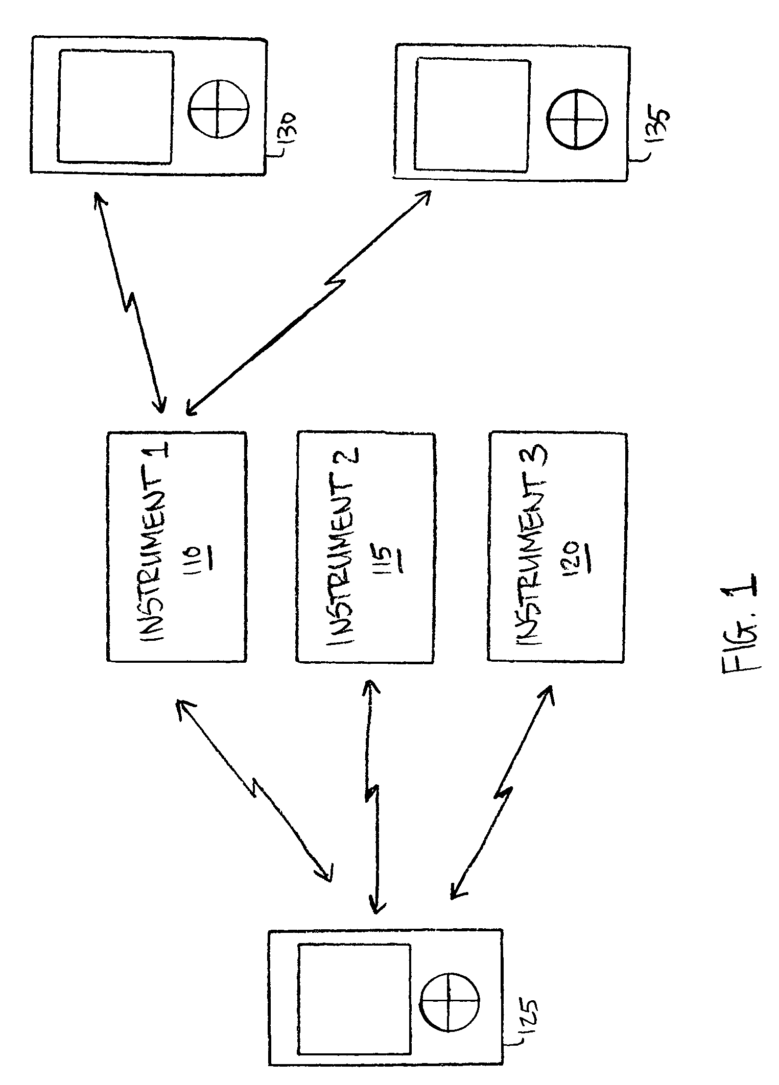
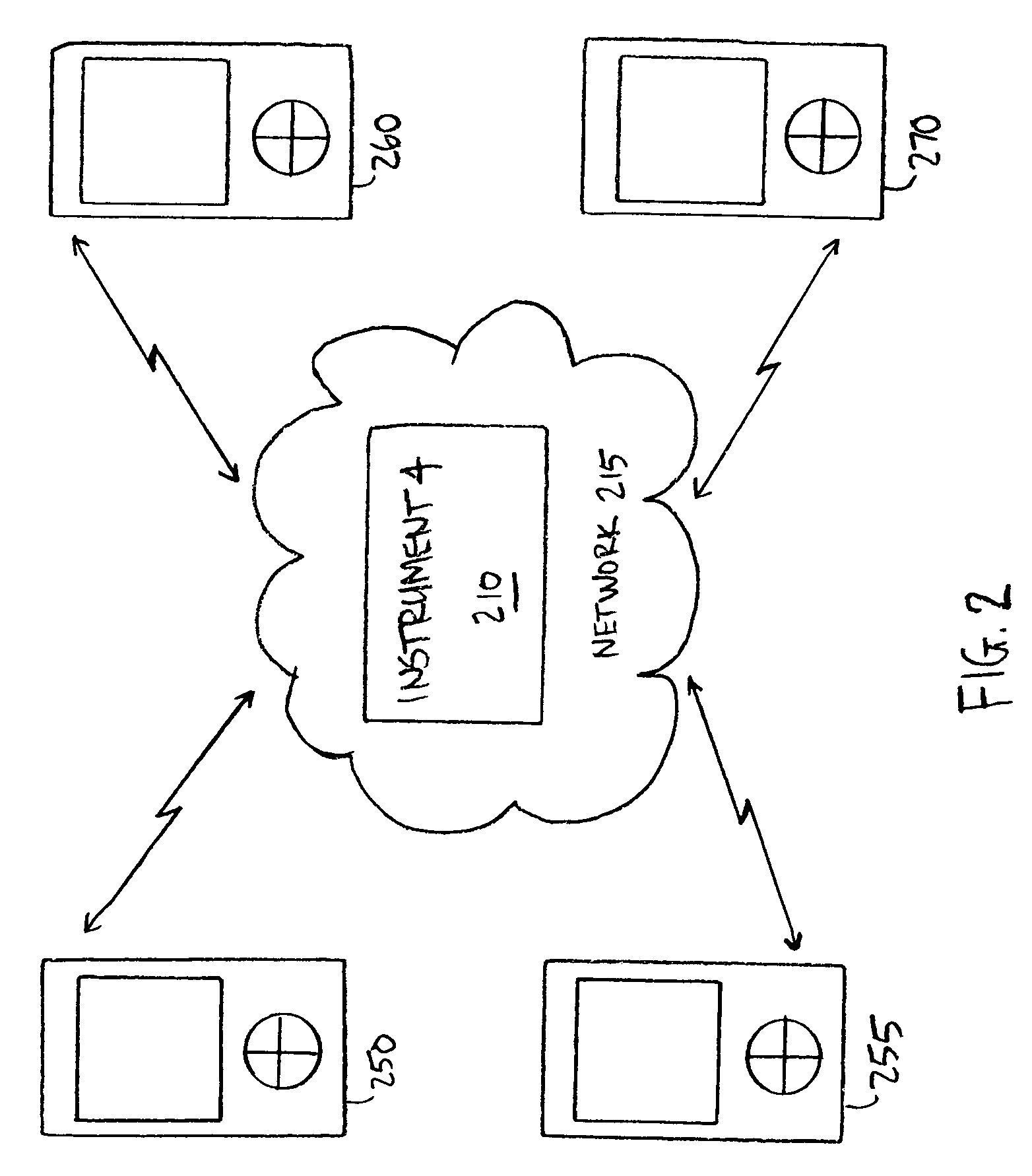
The patent describes a method for wireless communication of vehicle diagnostic information using a diagnostic instrument and a wireless adapter. The wireless adapter can control multiple diagnostic instruments and synchronize data from different instruments. The diagnostic instrument can also send data to multiple computing devices simultaneously and act as a network gateway for others. The technical effects of this patent include improved efficiency and convenience for diagnostic data collection and analysis.

Problems solved by technology

Although handheld computing devices offer portability and flexibility, the diagnostic instruments with which they are designed to work typically require serial communication cables or other wireline infrastructure to communicate.
Consequently much of a handheld computing device's portability is compromised when it must be coupled to a wireline interface.
Many such connections can become cumbersome for the technician to manage.
An improper or incorrect connection may cause the computing device to malfunction or to provide inaccurate information and, therefore, consume diagnostic or repair time needlessly.
Conventional wireline interfaces also complicate the use of diagnostic instruments for technician training or other collaborative work.
Using a single computing device can make it difficult for a group of users to view the results or to collaborate in the process.
Thus service facilities may be reluctant to reinvest in the costly replacement or redesign of their diagnostic instruments in order to have wireless capability.

Method used


Image

  • Wireless communication for diagnostic instrument
  • Wireless communication for diagnostic instrument
  • Wireless communication for diagnostic instrument

Examples


Embodiment Construction

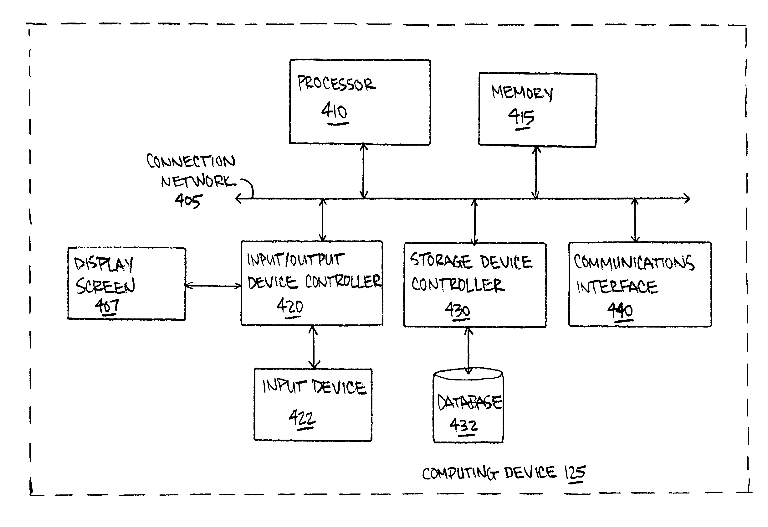
[0025]The present disclosure is now described more fully with reference to the accompanying figures, in which several embodiments are shown. The embodiments described herein may include or be utilized with any appropriate engine having an appropriate voltage source, such as a battery, an alternator and the like, providing any appropriate voltage, such as about 12 Volts, about 42 Volts and the like. The embodiments described herein may be used with any desired system or engine. Those systems or engines may comprise items utilizing fossil fuels, such as gasoline, natural gas, propane and the like, electricity, such as that generated by battery, magneto, solar cell and the like, wind and hybrids or combinations thereof. Those systems or engines may be incorporated into other systems, such as an automobile, a truck, a boat or ship, a motorcycle, a generator, an airplane and the like.

[0026]One skilled in the art will recognize that methods, apparatus, systems, data structures, and comput...


PUM


Abstract

A wireless interface for a diagnostic instrument is provided. The diagnostic instrument includes a communications interface having an external data port. A wireless adapter coupled to the external data port communicates diagnostic data with one or more computing devices. In a single user mode, a computing device can control several diagnostic instruments wirelessly. In broadcast mode, a diagnostic instrument can send a data stream wirelessly to many listening computing devices. Further features, such as safety warning messages, are provided.

Description

TECHNICAL FIELD[0001]The present disclosure relates generally to diagnostic instruments, and more particularly, to diagnostic instruments using wireless communication interfaces.BACKGROUND[0002]Conventional computing devices, such as PCs and handheld computers, provide a convenient platform for communicating with diagnostic instrumentation. The computing devices enable a technician to use a diagnostic instrument quickly and easily. For example, in an automotive service facility, a handheld computing device can be easily connected to a vehicle's on-board diagnostic system for testing or problem diagnosis.[0003]Although handheld computing devices offer portability and flexibility, the diagnostic instruments with which they are designed to work typically require serial communication cables or other wireline infrastructure to communicate. Consequently much of a handheld computing device's portability is compromised when it must be coupled to a wireline interface.[0004]In addition, a tec...

Claims


Application Information

Patent Timeline
Patent Type & Authority Patents(United States)
IPC IPC(8): G01M17/00G01R31/00G07C5/00G08C17/00
CPCG07C5/008
Inventor FUDALI, THOMAS M.NICHOLSON, WILLIAM D.
Owner SNAP ON INC
Learn More