Capacitance type dynamic quantity sensor

a dynamic quantity and capacitance technology, applied in the field of cap, can solve the problems of reducing the reliability of the sensor, increasing the manufacturing cost, and thickening of the total fixed electrode, so as to improve the manufacturing cost and yield, improve reliability, and eliminate the occurrence of film peeling of the electrod

Active Publication Date: 2007-06-05
ABLIC INC
View PDF6 Cites 15 Cited by
  • Summary
  • Abstract
  • Description
  • Claims
  • Application Information

AI Technical Summary

Benefits of technology

[0006]The present invention has been made in the light of the foregoing, and it is, therefore, an object of the present invention to provide an inexpensive capacitance type dynamic quantity sensor which prevents the generation of hillocks on surfaces of electrodes, and which prevents film peeling of the electrode to thereby increase the reliability of the capacitance type dynamic quantity sensor.
[0010]Consequently, even when the first and second fixed electrode is made of a single metallic material, it is possible to avoid the generation of hillocks on the surfaces of the fixed electrodes and to eliminate the occurrence of film peeling of the electrodes or the like. Therefore, the reliability can be enhanced. In addition, since an inexpensive material such as Al can be adopted for the first or second fixed electrode, it is possible to anticipate an improvement in manufacturing cost and yield as well as an improvement in fluctuation in thicknesses of the electrodes.
[0011]Since a plurality of grooves or holes are formed at fixed intervals in the first or second metallic electrode formed on the surface of the upper or lower substrate, even when the first or second fixed electrode is made of a single metallic material, it is possible to avoid the generation hillocks on the surface of the first or second fixed electrode. Consequently, it is possible to provide the highly reliable and inexpensive dynamic quantity sensor that prevents film peeling of the fixed electrodes.

Problems solved by technology

However, the adoption of the multilayer electrode structure increases the manufacturing cost.
Moreover, the film peeling of the two-layer electrode becomes liable to occur due to a difference between the thermal expansion coefficients of the different kinds of electrode layers, reducing reliability of the sensor.
As a result, the total fixed electrode becomes thick, and hence the fluctuation in the electrode thicknesses becomes liable to occur.

Method used


Image

  • Capacitance type dynamic quantity sensor
  • Capacitance type dynamic quantity sensor
  • Capacitance type dynamic quantity sensor

Examples


Embodiment Construction

[0020]A preferred embodiment of the present invention will hereinafter be described in detail by giving as an example an angular velocity sensor typifying a capacitance type dynamic quantity sensor of the present invention with reference to the accompanying drawings.

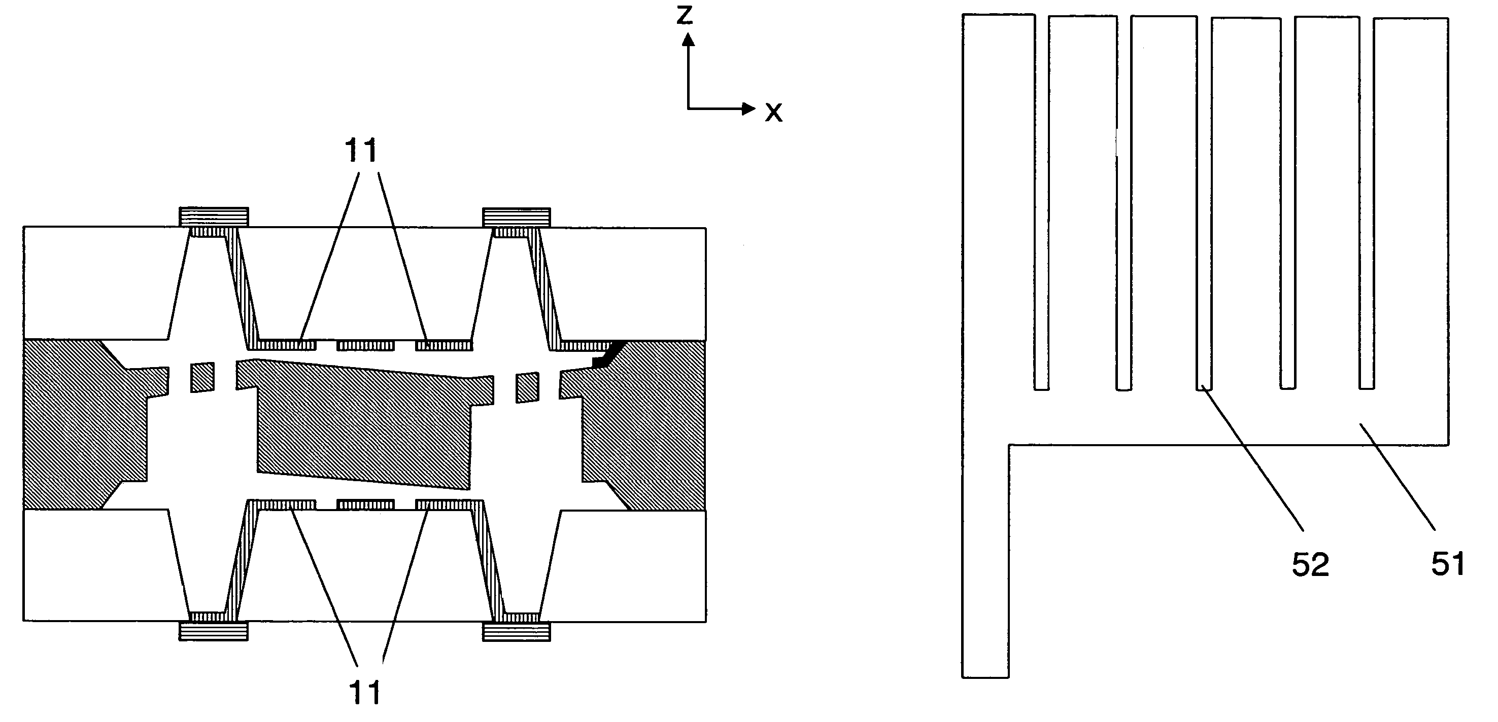
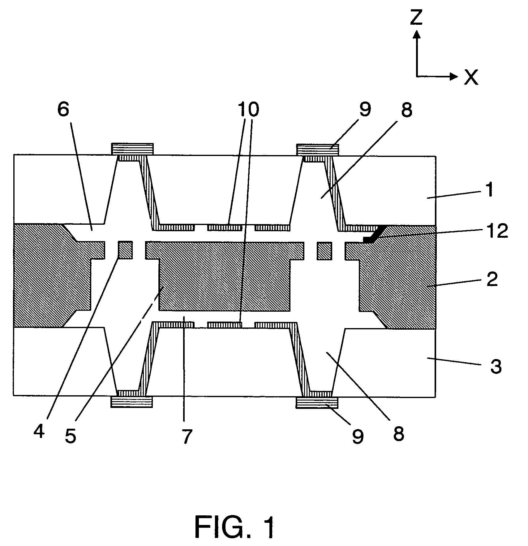
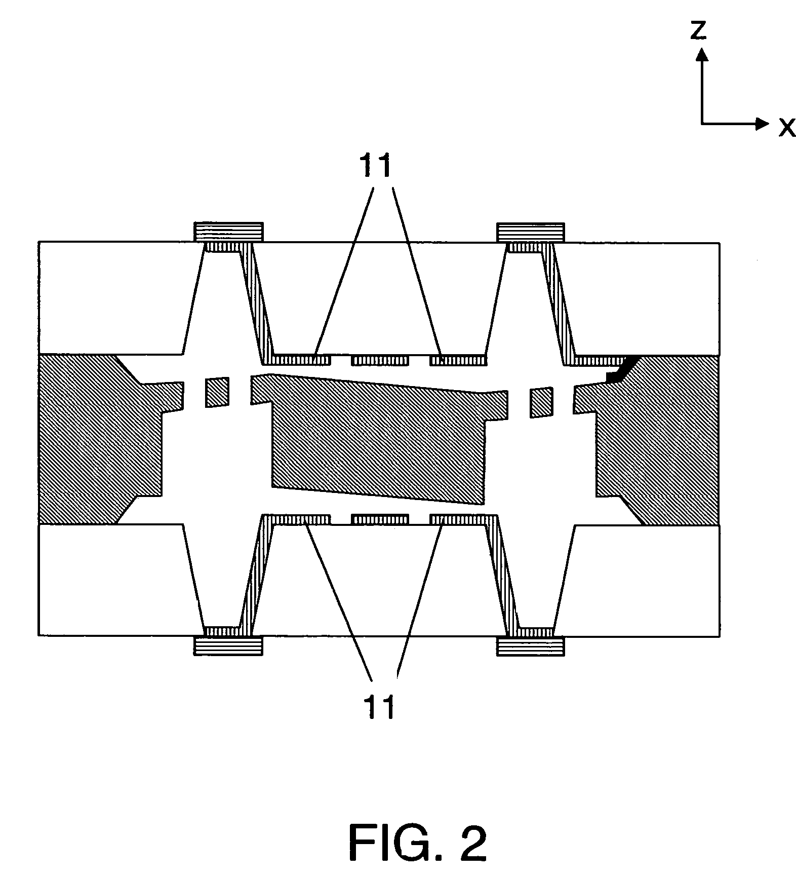
[0021]FIG. 1 shows a schematic cross sectional view of an angular velocity sensor according to an embodiment of the present invention. Referring to FIG. 1, this capacitance type dynamic quantity sensor has a three-layer structure including an upper glass substrate 1, (first substrate), a silicon substrate 2 (third substrate), and a lower glass substrate 3 (second substrate). These three substrate 1, 2 and 3 are joined to each other to form the three-layer structure. A vibration member having beams 4 and a weight 5 is formed within the silicon substrate 2 through the etching process. The vibration member is adapted to be vibrated or twisted due to an applied force from the outside (i.e., an external force). A shape of eac...


PUM


Abstract

A capacitance type dynamic quantity sensor has a first substrate, a second substrate disposed over the first substrate, and first and second electrodes each disposed on a main surface of a respective one of the first and second substrates. Each of the first and second electrodes has through-holes formed in a portion thereof. A third substrate is disposed between and connected to the main surface of each of the first and second substrates. A vibration member is mounted on the third substrate so as to confront the first and second electrodes with gaps therebetween. The vibration member is mounted on the third substrate to undergo vibrational movement in response to application of an acceleration or an angular velocity to the vibration member so that the capacitance type dynamic quantity sensor detects a dynamic quantity in accordance with a change in capacitance between the first and second electrodes due to vibrational movement of the vibration member.

Description

BACKGROUND OF THE INVENTION[0001]1. Field of the Invention[0002]The present invention relates in general to a sensor for detecting a dynamic physical quantity such as acceleration or angular velocity. In particular, the present invention relates to a capacitance type dynamic quantity sensor for detecting a dynamic physical quantity by detecting a change in capacitance due to displacement of a structure which is manufactured through a semiconductor process.[0003]2. Description of the Related Art[0004]Heretofore, there has been known a capacitance type dynamic quantity sensor in which a weight adapted to be displaced due to applied acceleration or angular velocity from the outside, and beams for supporting the weight are formed within a semiconductor substrate in order to detect a change in capacitance obtained between movable electrodes of the weight and fixed electrodes formed at a minute interval from the movable electrodes (refer to JP 08-094666 A for example) FIG. 7 is a schemati...

Claims


Application Information

Patent Timeline
Patent Type & Authority Patents(United States)
IPC IPC(8): G01P15/125G01C19/56G01P3/44G01C19/5719H01L29/84
CPCG01P15/125G01C19/5719G01P2015/084H01L29/84
Inventor KATO, KENJISUDO, MINORUYARITA, MITSUO
Owner ABLIC INC
Why Eureka
Try Eureka