Heat exchanger element and heat exchanger member for a stirling cycle refrigerator and method of manufacturing such a heat exchanger member

a technology of heat exchanger and stirling cycle refrigerator, which is applied in the direction of indirect heat exchangers, machines/engines, light and heating apparatus, etc., can solve the problems of affecting the efficiency etc., to achieve convenient handling of heat exchanger elements, enhance heat conductivity, and increase the contact area

Inactive Publication Date: 2007-06-05
SHARP KK
View PDF22 Cites 20 Cited by
  • Summary
  • Abstract
  • Description
  • Claims
  • Application Information

AI Technical Summary

Benefits of technology

[0026]Integrally forming the annular corrugate fin and the outer ring-shaped member helps increase the area of contact between them and thereby enhance heat conductivity. Moreover, their integration makes the handling of the heat exchanger element easy, and makes the repair, by replacement, of the heat exchanger element possible. This makes the heat exchanger element very economical and recyclable. The integration is achieved by a bonding means, such as brazing or soldering.
[0027]A heat exchanger member according to the present invention is produced by inserting the above-described heat exchanger element for a Stirling cycle refrigerator into a hollow portion of a tubular body. In this case, the internal diameter of the body may be mad...

Problems solved by technology

Thus, this process takes too much trouble and time, hindering the improvement of productivity and the reduction of manufacturing costs.
Moreover, the heat exchanger member thus manufactured is prone to variations in quality, specifically in heat exchange performance, and thus tends to lack in stability and reliability.
Furthermo...

Method used


Image

  • Heat exchanger element and heat exchanger member for a stirling cycle refrigerator and method of manufacturing such a heat exchanger member
  • Heat exchanger element and heat exchanger member for a stirling cycle refrigerator and method of manufacturing such a heat exchanger member
  • Heat exchanger element and heat exchanger member for a stirling cycle refrigerator and method of manufacturing such a heat exchanger member

Examples


first embodiment

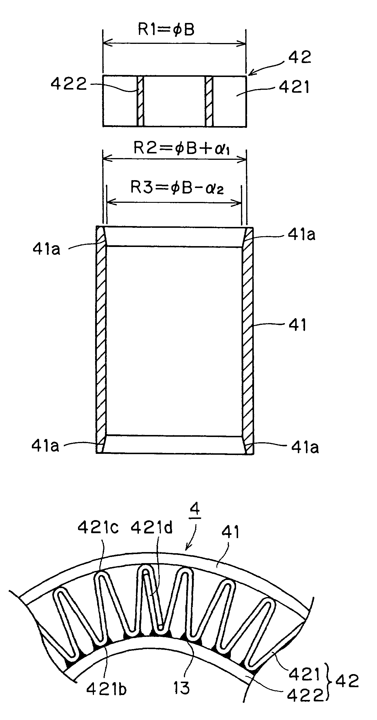
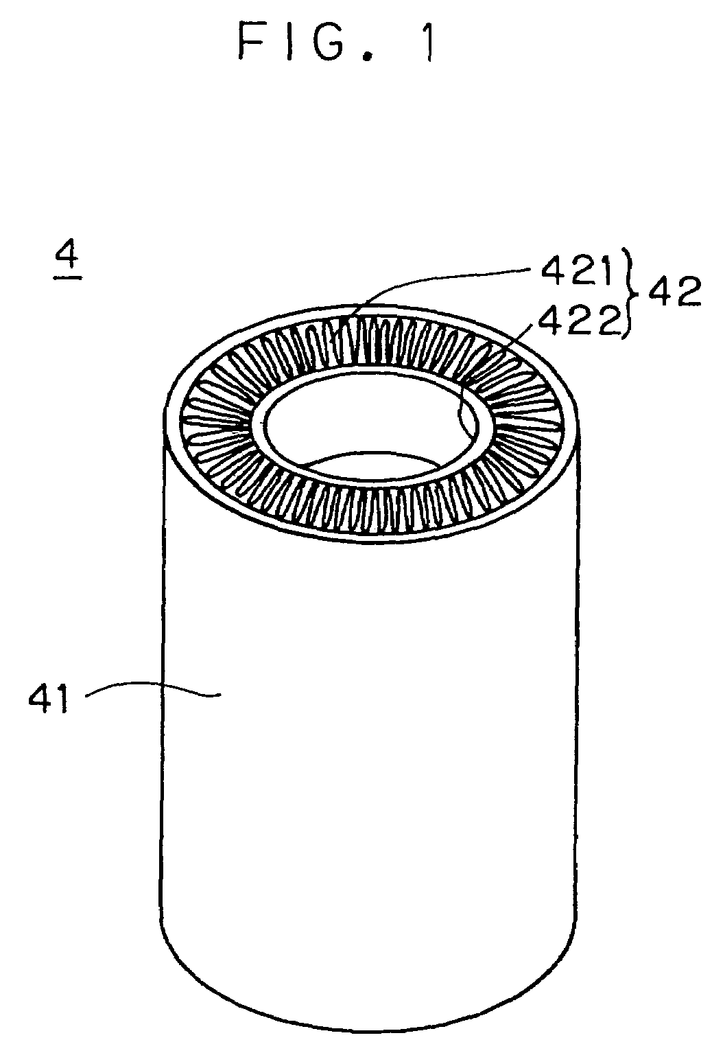
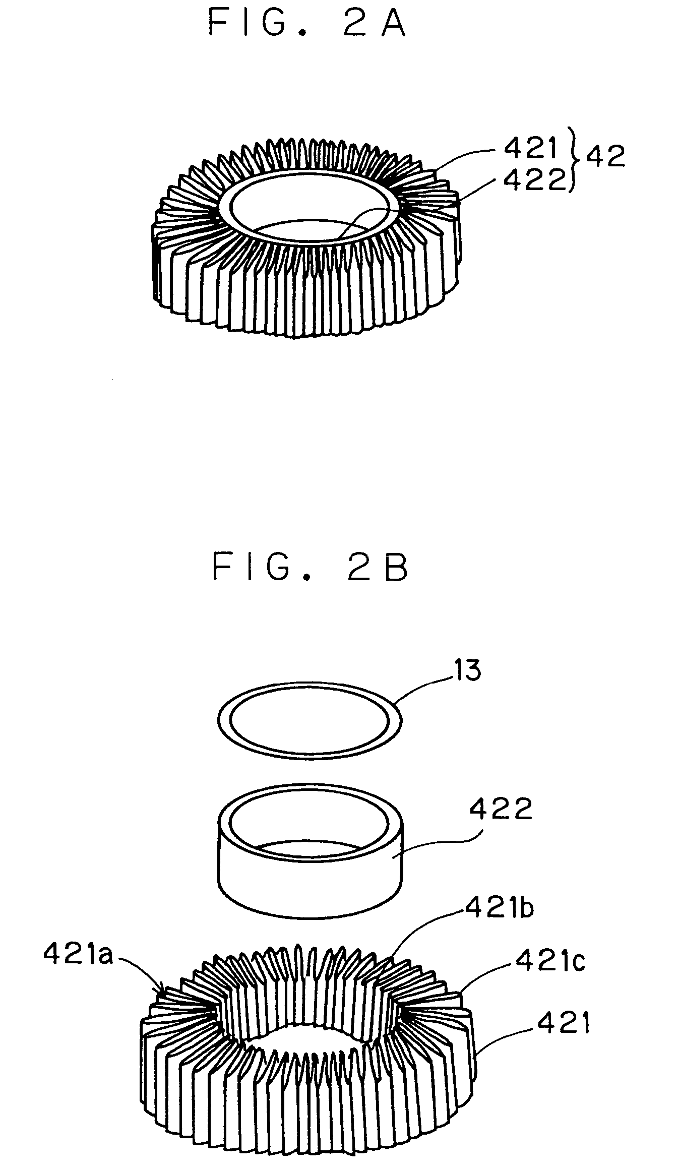
[0084]the invention will be described below. FIG. 1 is an external perspective view of the heat rejector 4 serving as a heat exchanger member in this embodiment. FIGS. 2A and 2B are an external perspective view and an exploded perspective view, respectively, of the heat exchanger element 42 of the heat rejector 4. FIG. 3 is an enlarged plan view of a portion of the heat rejector, as seen axially.

[0085]This heat exchanger element 42 is composed of an annular corrugate fin 421 and an inner ring-shaped member 422. The annular corrugate fin 421 is produced by forming a corrugated sheet material into a cylindrical shape with the individual grooves 421a thereof parallel to the axis of the cylindrical shape. The inner ring-shaped member 422 is a cylindrical member made of a material having good thermal conductivity.

[0086]First, the manufacturing method of the annular corrugate fin 421 used in this embodiment will be described. FIGS. 6A to 6C show the manufacturing procedure of the annular ...

eighth embodiment

[0184]Next, the invention will be described. FIG. 20 is an external perspective view of the heat rejector 4 serving as a heat exchanger member in this embodiment. FIG. 21A is an external perspective view and an exploded perspective view, respectively, of the heat exchanger element 42′ incorporated in the heat rejector 4.

[0185]This heat exchanger element 42′ is composed of an annular corrugate fin 421 and an outer ring-shaped member 422′. The annular corrugate fin 421 is produced by the same procedure as described earlier in connection with the first to seventh embodiments. The outer ring-shaped member 422′ is a cylindrical member made of a material having good thermal conductivity and resilience.

[0186]As FIG. 21A shows, the outer ring-shaped member 422′ is placed in contact with the outer periphery of the annular corrugate fin 421 so that they are coaxial with each other. Here, the external diameter of the annular corrugate fin 421 is made substantially equal to the internal diamete...

ninth embodiment

[0191]Next, the invention will be described with reference to the drawings. FIG. 24 is an enlarged plan view of a portion of the heat rejector 4 of the embodiment, as seen axially. FIG. 25 shows part of the manufacturing procedure of the heat rejector 4; specifically, FIGS. 25A and 25B are respectively sectional views of the heat rejector before and after the heat exchanger element 42 is inserted into it from the guide member side thereof.

[0192]As FIGS. 25A and 25B show, a cylindrical body 41 is fixed, together with a guide member 14, to a jig 15, with the axis of the body 41 kept substantially horizontal. The guide member 14 is provided so as to abut the body 41, and has an external diameter substantially equal to that of the body 41. The guide member 14 is so formed as to have a tapered cross section inside, forming a tapered portion 14a, so that its internal diameter is equal to the internal diameter of the body 41 at the joint and increases away therefrom.

[0193]Now, the manufact...


PUM

PropertyMeasurementUnit
Diameteraaaaaaaaaa

Abstract

A heat exchanger element for a Stirling cycle refrigerator is produced by integrally forming an annular corrugate fin that is produced by forming a sheet material, corrugated so as to have a large number of grooves, into a cylindrical shape with the grooves parallel to an axis of the cylindrical shape and an inner ring-shaped member that is placed in contact with the inner periphery of the annular corrugate fin. A heat rejector or heat absorber for a Stirling cycle refrigerator is produced by inserting this heat exchanger element into the hollow portion of a tubular body.

Description

[0001]This application is the national phase under 35 U.S.C. § 371 of PCT International Application No. PCT / JP01 / 07515 which has an International filing date of Aug. 30, 2001, which designated the United States of America.BACKGROUND OF THE INVENTION[0002]1. Field of the Invention[0003]The present invention relates to a heat exchanger member, such as a heat absorber or heat rejector, provided in a Stirling cycle refrigerator, to a heat exchanger element for use in such a heat exchanger member, and to a method of manufacturing such a heat exchanger member.[0004]2. Description of the Related Art[0005]First, a typical configuration of a free-piston-type Stirling cycle refrigerator exploiting a Stirling cycle will be described. FIG. 29 is a diagram schematically showing a section, as seen from the side, of a free-piston-type Stirling cycle refrigerator. Inside a cylinder 1, a heat absorber 2 acting as a low-temperature portion, a regenerator 3, and a heat rejector 4 acting as a high-temp...

Claims


Application Information

Patent Timeline
IPC IPC(8): F28D17/00F02G1/055F25B9/14F28F1/10F28F1/40F28F13/06
CPCF02G1/055F25B9/14F28F1/105F28F1/40F28F13/06F28D17/00F25B2500/01Y10T29/4935
Inventor MOCHIZUKI, HITOSHIOGURA, YOSHIAKI
Owner SHARP KK
Why Eureka
Try Eureka