Environment protector air compressor pressurized wheel hub

a technology for air compressors and hubs, applied in the direction of hubs, shafts and bearings, vehicle components, etc., can solve the problems of wheel assembly loss, dangerous scenario of property and possibly life endangerment, bearing and race will typically disintegra

Inactive Publication Date: 2007-06-05
AIR TIGHT
View PDF26 Cites 13 Cited by
  • Summary
  • Abstract
  • Description
  • Claims
  • Application Information

AI Technical Summary

Benefits of technology

[0014]Another objective of the instant invention to provide a means for maintaining a predetermined amount of pressurized air in axle hub assemblies which is automatically adjusted despite large flucuations in temperature such as those found with a trailer is submersed in very warm or very cold water.
[0016]Still another objective of the instant invention is to provide an indicator for law enforcement that hub integrity is intact before allowing trailer placement within a body of water thereby preventing a leaking hub from contamination of water with oil byproducts.
[0017]Still another objective of the instant invention is to provide an indicator for law enforcement that hub integrity is intact during trailer placement within a body of water thereby indicating a leaking hub that might otherwise be concealed by placement under the surface of the water.
[0018]Yet still another objective of the instant invention is to provide a positive pressure within the hub at all times to prevent the entrance of particles within the hub including water thereby preventing premature destruction of the wheel bearing assemblies.
[0020]The wheel hub comprises a sealing arrangement that provides an air-tight sealing arrangement for the bearings of a wheel hub to form a closed air system in the interior of the wheel hub. An aperture is formed through the axle to provide an air flow connection with a remotely mounted air compressor used to pressurize the closed air space through the aperture. An air pressure gauge provides a visual indication of the level of air pressure in the closed air system whereby a breached seal condition within the wheel hub can be detected by the inability to maintain a pressurized system. The hub cap may also be used to provide a seal wherein the degradation of the hub bearing outer seal will not result in air loss or grease leakage.

Problems solved by technology

Absence of a lubricant can quickly lead to catastrophic failure of the bearings causing hub disengagement of the axle, which can result in wheel assembly loss and the associated dangerous scenario of property and possibly life endangerment.
For instance, a trailer carrying a heavy load such as a 25 foot boat, will quickly heat up a bearing that is not properly lubricated.
Should the bearing fail, the bearing and race will typically disintegrate with a likely result of the hub and wheel detaching from the axle of the trailer.
Boat trailers present an excellent example of premature wear as a boat trailer is typically inserted into water for loading or unloading of the boat.
Should there be a failure of the hub seal, water is allowed to enter the hub resulting in the premature wear.
In addition, should the water be saltwater, bearing disintegration is greatly enhanced since rust forming on the bearing surfaces will operate to destroy the bearings with very short use.
However, should the hub seal fail, the assembly will actually facilitate grease being pushed through the seal.
Should the spring jam, even if the bearing indicator illustrate that grease is prevalent in the seal, it may be providing a false indication.
Unfortunately, a spring loaded system to pressurize grease into the hub results in an excess amount of grease injected into the hub for proper operation.
This results in an obvious waste of grease for only the bearing rollers must be lubricated.
Of course, the grease continues to leak from the wheel hub because the breach in the seal remains.
The constant expulsion of grease into natural waters by the prior art bearing lubrication systems will have a cumulative negative impact on the environment.
Should the water be a reservoir for drinking water, even a few drops of oil can result in system contamination.
However, it is well known that any oil in water has an adverse effect to wildlife.

Method used


Image

  • Environment protector air compressor pressurized wheel hub
  • Environment protector air compressor pressurized wheel hub
  • Environment protector air compressor pressurized wheel hub

Examples


Embodiment Construction

[0023]Although the invention will be described in terms of a specific embodiment, it will be readily apparent to those skilled in this art that various modifications, rearrangements, and substitutions can be made without departing from the spirit of the invention. The scope of the invention is defined by the claims appended hereto.

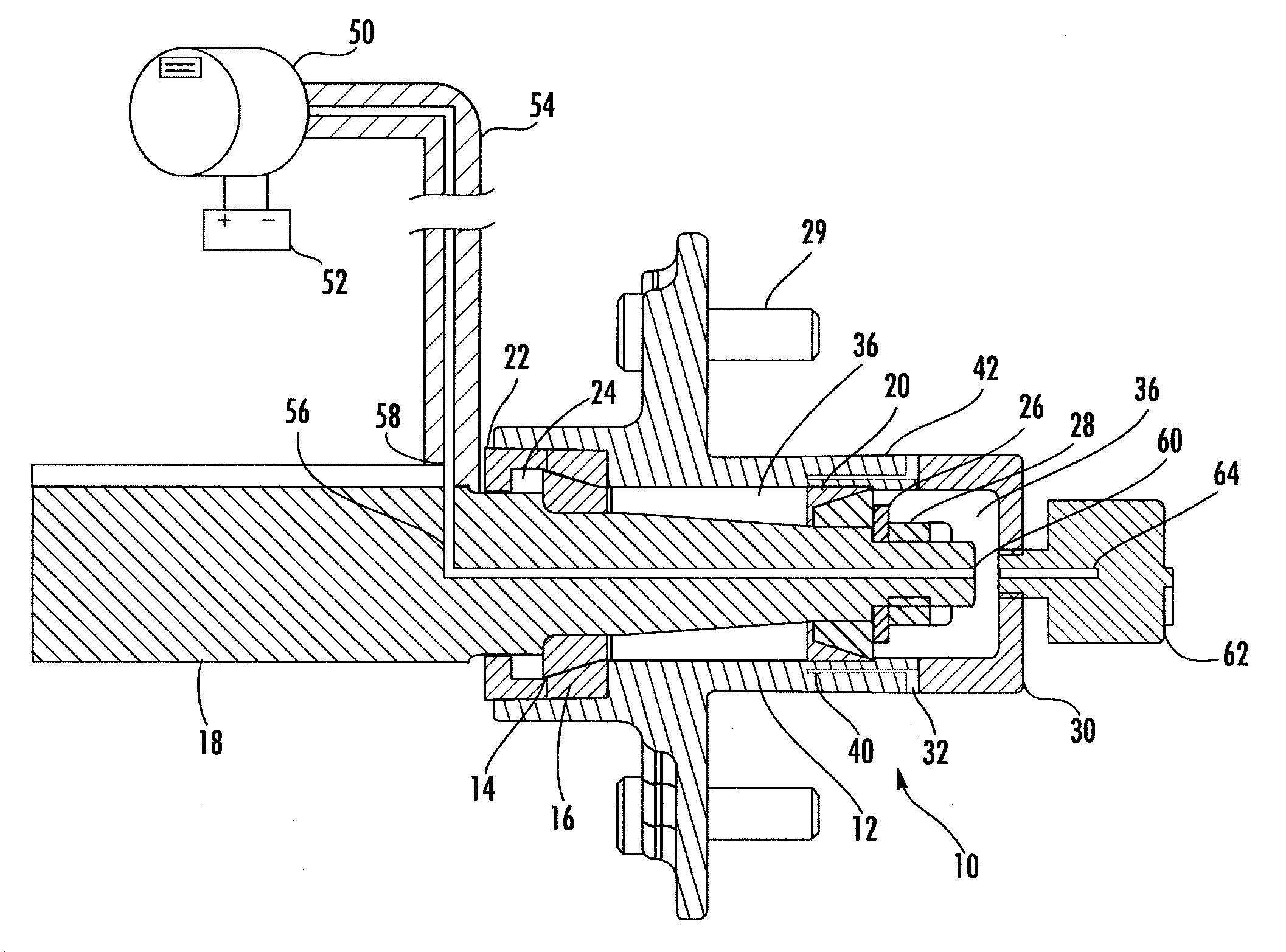
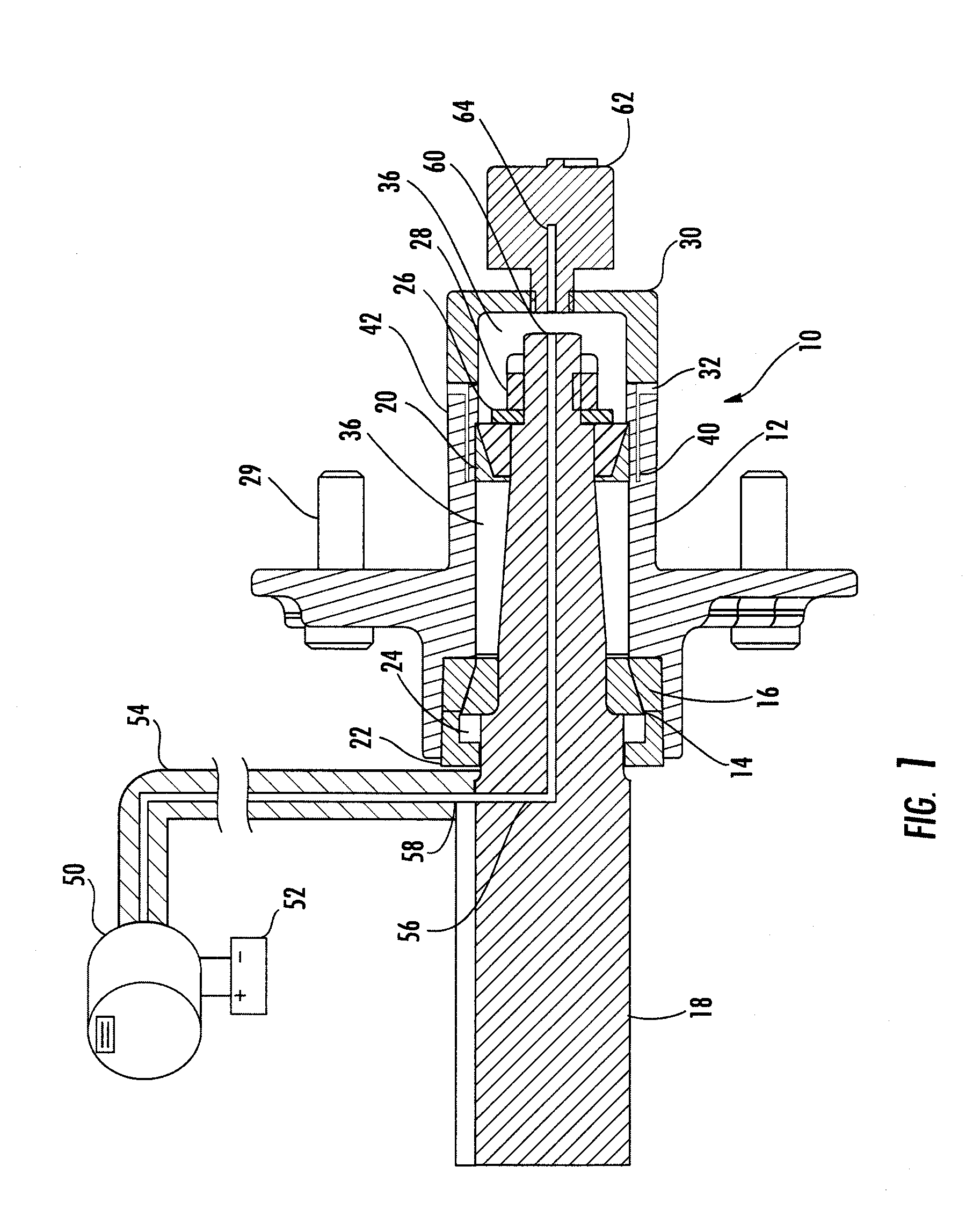
[0024]FIG. 1 is a cross-sectional side view of a wheel hub assembly 10 constructed from a hub 12 rotatably supported on inner bearing 14 operatively associated with inner bearing race 16, and outer bearing 18 operatively associated with outer bearing race 20. A modified oil seal 22 has a seal 24 capable of sealing air. The hub 12 is secured to the axle 18 by use of a washer 26 and nut 28 connection, wheel coupling bolts 29 are shown for reference. A cap 30, commonly referred to as a dust cap, includes a seal 32 capable of sealing air. The space between the cap 30 and the oil seal 22 forming a enclosure defined as the closed air space 36. The cap 30 has an ...


PUM


Abstract

A pressurized wheel hub formed from an air-tight sealing arrangement located on each end of a wheel hub to form a closed air system in the interior of the wheel hub. The closed air system fluidly coupled to a DC power air compressor for receiving pressurized air. A pressure gauge provides a visual indication of the air pressure in the closed air system whereby a breached seal condition within the wheel hub can be detected.

Description

RELATED APPLICATION[0001]This application is a continuation-in-part of patent application Ser. No. 10 / 376,756, filed Feb. 28, 2003.FIELD OF THE INVENTION[0002]This invention is related to the field of wheel hubs and, in particular, to a apparatus that permits the pressurization of a wheel hub to indicate hub seal integrity.BACKGROUND OF THE INVENTION[0003]This is an improvement of our pressurized wheel hub disclosed in the above captioned patent application for use in pressurizing the wheel hub automatically. By way of background, a conventional boat trailer utilizes a fixed axle secured to a trailer frame. A wheel assembly is coupled to the axle by use of a wheel hub. The wheel hub employs a bearing assembly to allow free rotation of the hub in relation to the axle. Thus, the wheel assembly, which includes the tire, permits transportation of the boat trailer over a road when trailered by an automobile. The conventional wheel hub employs bearings, namely an inner and outer bearings ...

Claims


Application Information

Patent Timeline
Patent Type & Authority Patents(United States)
IPC IPC(8): B60B27/00F16C33/76B60B27/02
CPCB60B27/02F16C33/76B60B27/0073B60B27/001
Inventor DOMBROSKI, HENRYCUNNINGHAM, ANTHONY
Owner AIR TIGHT
Why Eureka
Try Eureka