
Lamp for an underwater camera

Inactive Publication Date: 2007-06-05
UPMEYER ARNOLD
View PDF7 Cites 5 Cited by
  • Summary
  • Abstract
  • Description
  • Claims
  • Application Information

AI Technical Summary

Benefits of technology

[0007]It is the problem of this invention to create a lamp for an underwater camera that is compact in size, has a low power consumption, and provides high-definition, true color photographs or film takes in the macrorange under water.
[0010]A lamp of this design can produce color neutral daylight at a color temperature of about 5,500° K. The inclination of the LED lamps towards the optical axis focuses the light volume on the macrorange so that the depth of field of the shots is improved and reduces reflection of the light irradiated in the water from particles in the water so that definition and color quality of the shots are considerably increased. As the dimensions of the lamp are rather small according to the design of the invention, a high irradiance can be achieved in a limited illuminated space. The great luminous angle of the LED lamps and the resulting even intermixture of irradiated light facilitate a virtually shadow-free illumination of the objects to be photographed in the macrorange. The small dimensions make it possible to use the underwater camera combined with the lamp according to the invention where space is limited, such as in narrow gaps and small caves under water. Among other advantages are low power consumption and the resulting long operating time, shockproof design, and easy handling. Existing cameras can easily be retrofitted with the lamp according to the invention. The camera can also be used when the lamp is separated from it. When filming or photographing animals under water, another beneficial effect of the lamp according to the invention is that the animals remain in the dome of light when the light is switched on because they naturally flee from the bright light into the dark, here towards the dark front window. The lamp, as it were, captures the animal and allows high-quality shots over a longer period of time. The lamp according to the invention has been described as yet in conjunction with underwater cameras. However, it can in general be used with conventional cameras as well.

Problems solved by technology

It often takes a tremendous effort to shoot high-quality pictures or films under water because of its natural turbidity due to particles and microorganisms dissolved or floating in the water.
The particles dissolved or floating in the water are present at such a high density that it is very difficult to obtain shots that show true colors and are in focus even if the camera is located very close to the object to be photographed, for example, an animal at a range of up to 12 inches.
However, underwater cameras designed like that are primarily intended for industrial photography and require considerable extra equipment.
Such sophisticated and expensive cameras are not suited for skin and scuba divers that want to photograph plants and animals.
Such underwater lamps are either rather bulky and heavy or do not have the required luminous intensity.
This underwater camera design is big, bulky, and expensive.
Its power consumption is high, and the object can only be illuminated for producing sharply defined and true color shots because of complicated and costly flushing with clean water.
Using the conventional underwater lamps for shooting photos and films involving animals has the disadvantage that some animals flee when the light is switched on, which makes shots in the macrorange quite difficult.

Method used


Image

  • Lamp for an underwater camera
  • Lamp for an underwater camera
  • Lamp for an underwater camera

Examples


Embodiment Construction

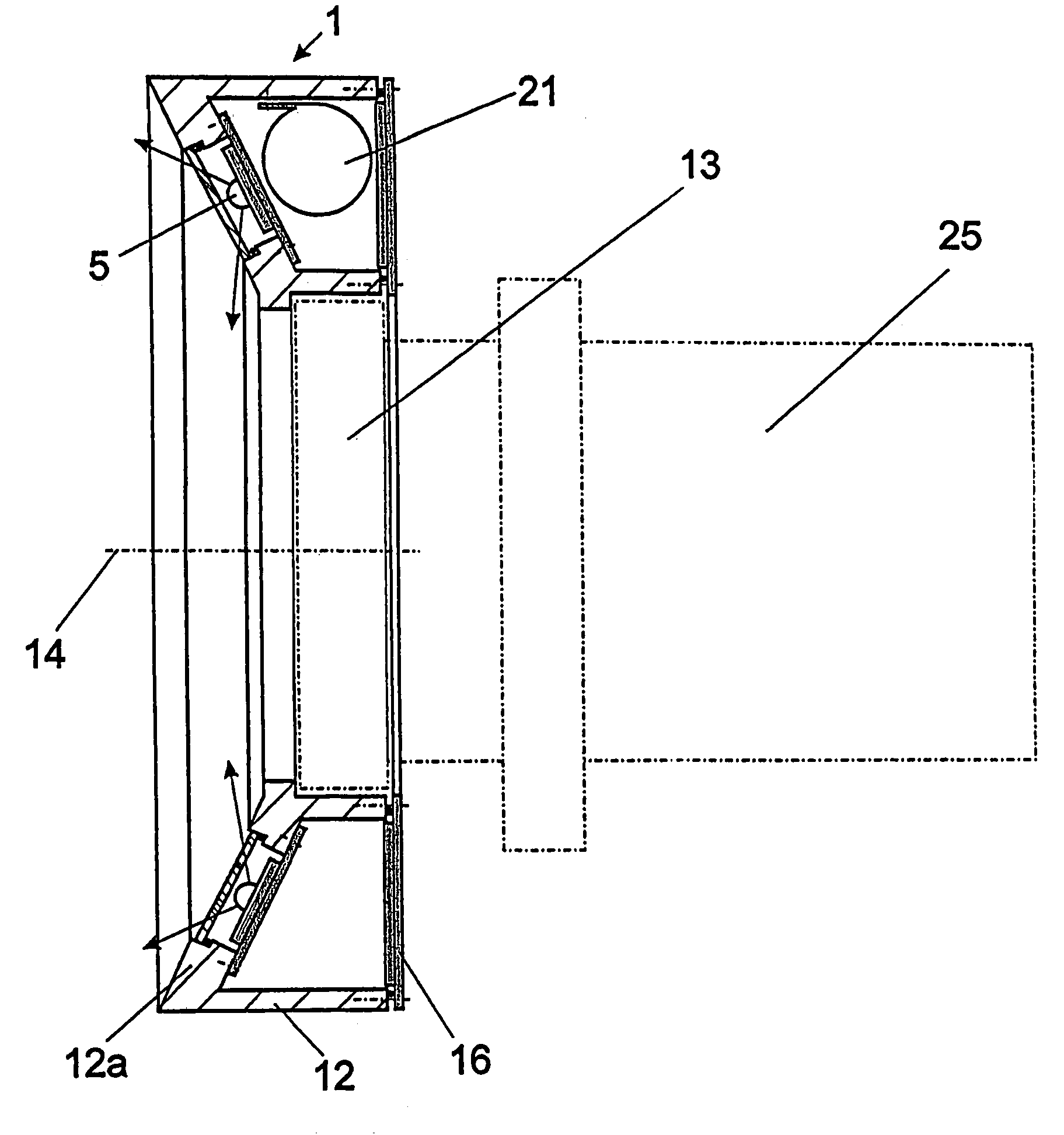
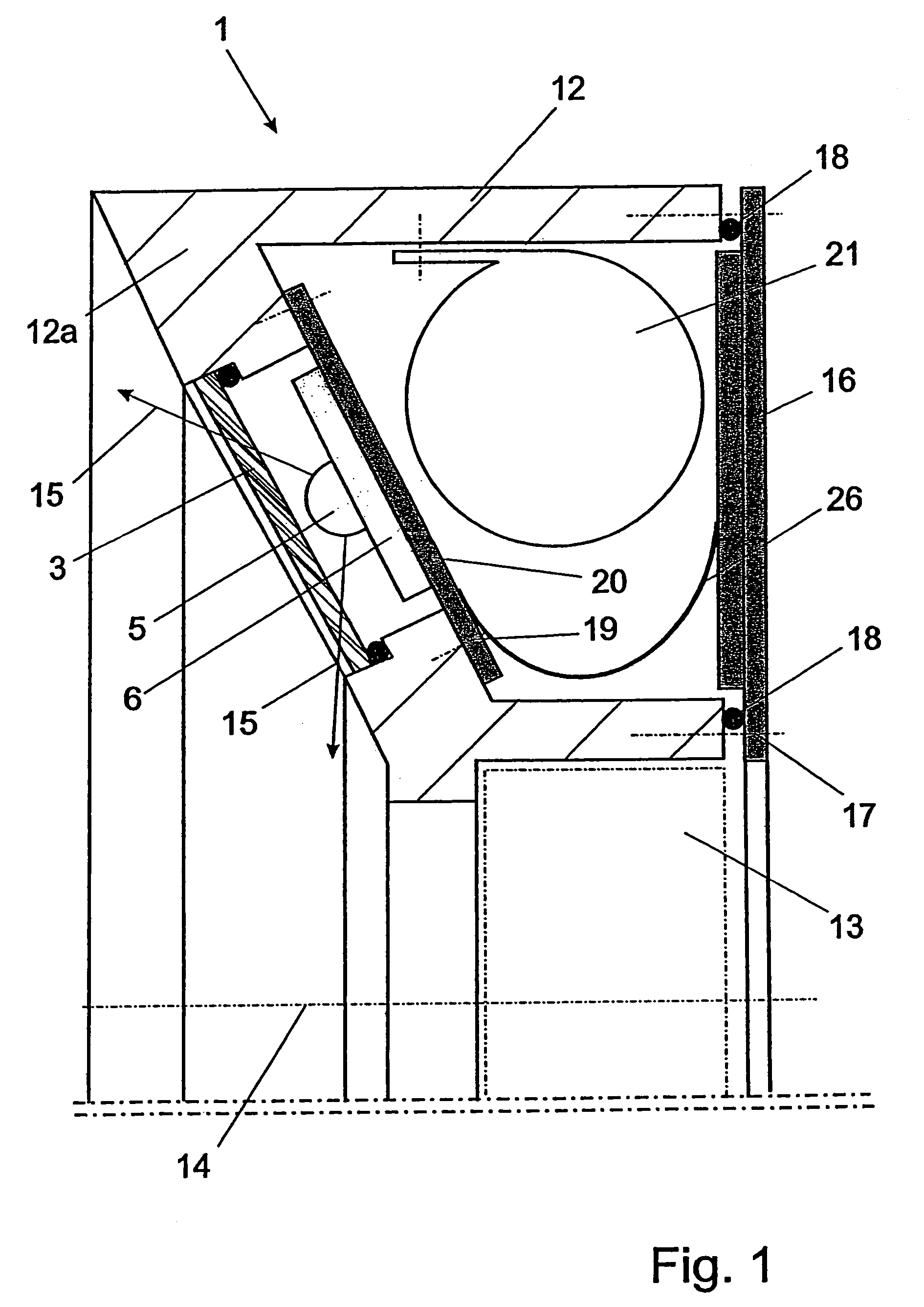
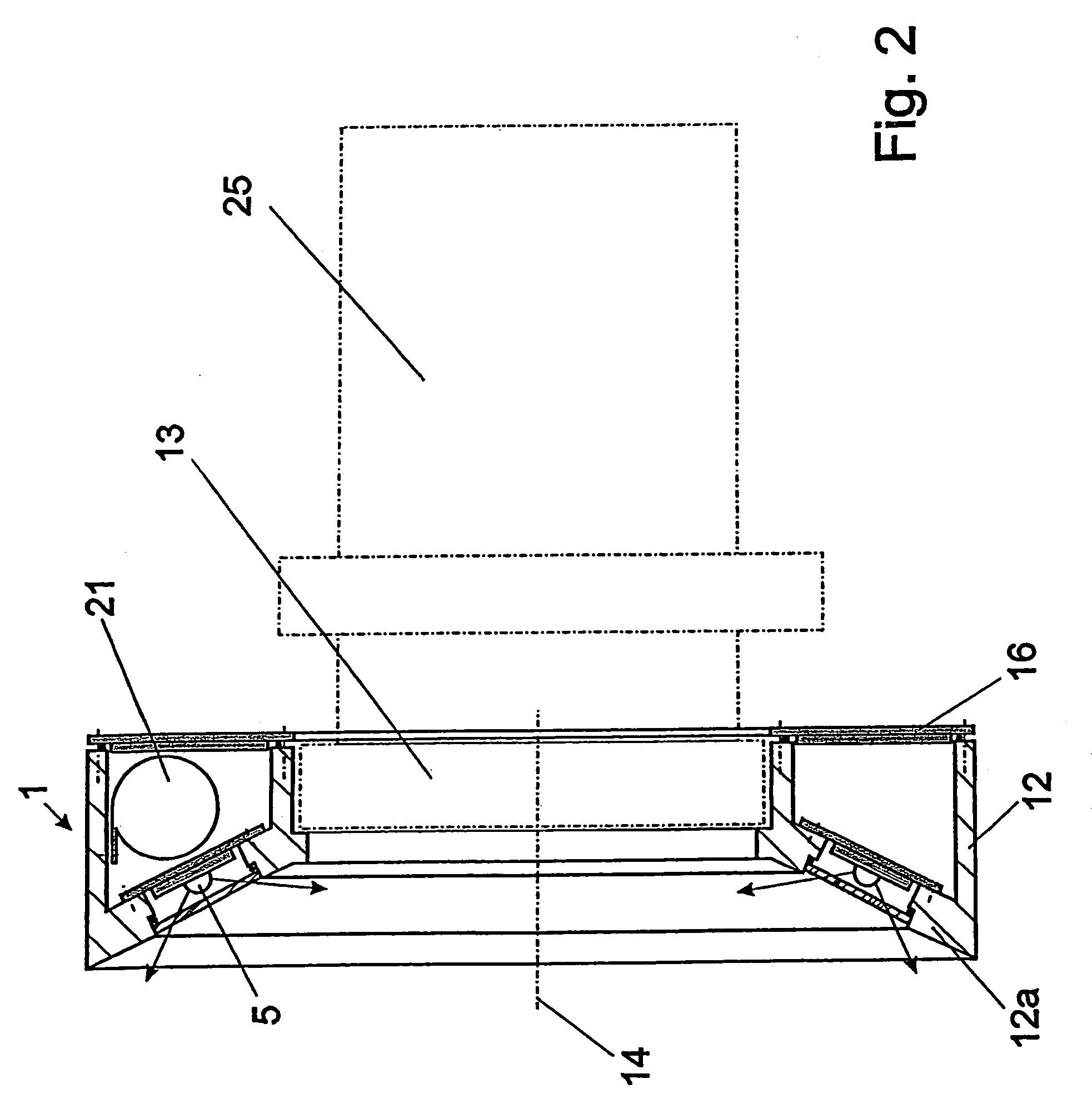
[0022]The LED lamp 1 shown in FIG. 5, a minimum of three of which form an underwater lamp for shots in the macrorange consists of a bowl-type lamp body 2 whose open side is covered by a window 3. An O-ring 4 seals the area between the lamp body 2 and the window 3. The light source is a diode emitting white light 5 that has an output of 1 watt in the embodiment described here. The LED lamp can alternatively be sealed by welding because the LED lamps need not be replaced. The light-emitting diode 5 is mounted to a cooling plate 6 that contacts the lamp body 2 via a cooling paste 7. This allows rapid heat removal from the light-emitting diode 5 to the lamp body 2 that preferably consists of aluminium. The light-emitting diode 5 is surrounded by a reflector 8. The lamp body 2 comprises a tapped hole 9 for fastening the LED lamp 1 to the outer side of a holding ring 24 (FIG. 4) that can be detachably mounted to the front side of the housing of an underwater camera 25 and is arranged conc...


PUM


Abstract

A lamp for an underwater camera to illuminate and photograph or film objects in the macrorange including a minimum of three LED diodes that emit white light which are arranged concentrically and at the same distance from each other around, and at a specific angle to, the optical axis of an underwater camera. An annular lamp holder may be used or the lamps may be directly integrated into the housing of the camera.

Description

BACKGROUND OF THE INVENTION[0001]1. Field of the Invention[0002]This invention relates to a lamp for an underwater camera for lighting and photographing and filming in the macrorange.[0003]2. Description of the Related Art[0004]It often takes a tremendous effort to shoot high-quality pictures or films under water because of its natural turbidity due to particles and microorganisms dissolved or floating in the water. The particles dissolved or floating in the water are present at such a high density that it is very difficult to obtain shots that show true colors and are in focus even if the camera is located very close to the object to be photographed, for example, an animal at a range of up to 12 inches.[0005]Various proposals have been made to supply clean water to the area in front of the camera to prevent the disadvantages of water turbidity and be able to shoot high-definition, true color photographs. DE 41 42 223 or DE 17 37 670, for example, describe an engineering solution ba...

Claims


Application Information

Patent Timeline
IPC IPC(8): G03B15/02B63C11/52F21L4/00F21S9/02F21V23/04F21V31/00F21V33/00G03B17/08
CPCB63C11/52F21V31/00F21V33/0052G03B17/08F21S9/02F21V23/04F21Y2101/02F21Y2115/10
Inventor UPMEYER, ARNOLD
Owner UPMEYER ARNOLD
Learn More